How to Use EXP-MSP430F5529LP: Examples, Pinouts, and Specs
Introduction
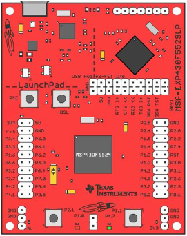
The EXP-MSP430F5529LP, manufactured by Texas Instruments, is a development board featuring the MSP430F5529 microcontroller. This microcontroller is optimized for low-power applications and includes a rich set of peripherals such as USB, LCD support, and multiple I/O options. The board is part of the LaunchPad series, designed to simplify prototyping and testing for embedded systems.
Explore Projects Built with EXP-MSP430F5529LP


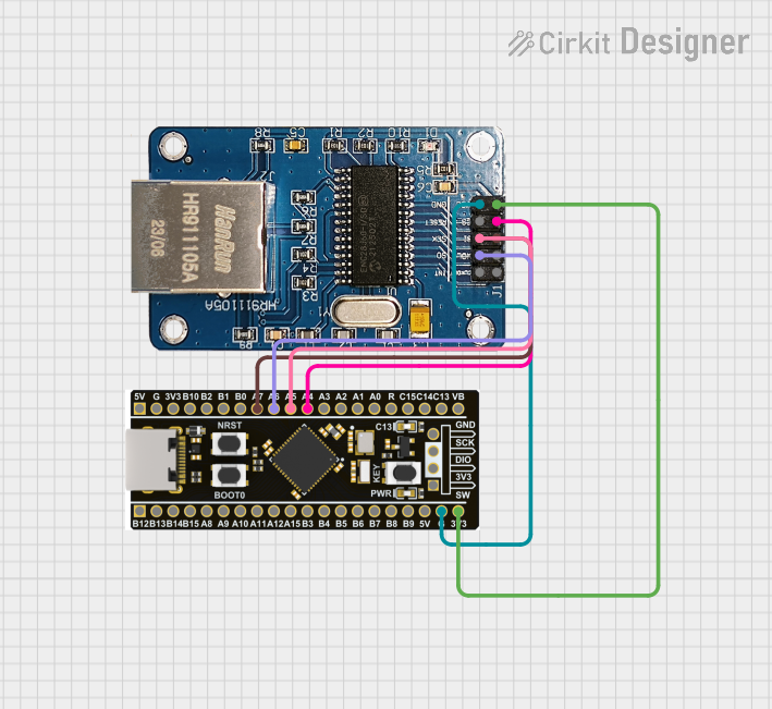
Explore Projects Built with EXP-MSP430F5529LP
Common Applications and Use Cases
- Low-power embedded systems
- USB-based applications
- Sensor interfacing and data acquisition
- Prototyping IoT devices
- Educational and research projects
Technical Specifications
Key Technical Details
| Specification | Value |
|---|---|
| Microcontroller | MSP430F5529 (16-bit RISC architecture) |
| Operating Voltage | 3.3V |
| Input Voltage Range | 3.3V to 5.0V |
| Clock Speed | Up to 25 MHz |
| Flash Memory | 128 KB |
| RAM | 8 KB |
| Communication Interfaces | USB, UART, SPI, I2C |
| GPIO Pins | 40 (multiplexed with other functions) |
| Onboard Debugger | eZ-FET Lite |
| USB Support | Full-speed USB 2.0 |
| Power Consumption | Ultra-low power (active and sleep modes) |
Pin Configuration and Descriptions
The EXP-MSP430F5529LP features a dual-row header pin layout. Below is a summary of the key pins and their functions:
| Pin Number | Pin Name | Description |
|---|---|---|
| P1.0 | GPIO/ADC | General-purpose I/O or ADC input |
| P1.1 | GPIO/UART_RX | General-purpose I/O or UART receive |
| P1.2 | GPIO/UART_TX | General-purpose I/O or UART transmit |
| P2.0 | GPIO/SPI_CLK | General-purpose I/O or SPI clock |
| P2.1 | GPIO/SPI_MOSI | General-purpose I/O or SPI data out |
| P2.2 | GPIO/SPI_MISO | General-purpose I/O or SPI data in |
| P4.7 | USB_DP | USB data positive |
| P4.6 | USB_DM | USB data negative |
| P6.0-P6.7 | ADC Channels | Analog-to-digital converter inputs |
| 3V3 | Power | 3.3V power output |
| GND | Ground | Ground connection |
For a complete pinout diagram, refer to the official Texas Instruments documentation.
Usage Instructions
How to Use the Component in a Circuit
Powering the Board:
- The board can be powered via the USB connection or an external 3.3V-5V power supply.
- Ensure the power source is stable and within the specified voltage range.
Programming the Microcontroller:
- Use the onboard eZ-FET Lite debugger to program the MSP430F5529.
- Compatible IDEs include Code Composer Studio (CCS) and Energia.
Connecting Peripherals:
- Use the GPIO pins for interfacing with external devices such as sensors, LEDs, or motors.
- For USB-based applications, connect the USB_DP and USB_DM pins to the USB interface.
Using Communication Protocols:
- Configure UART, SPI, or I2C in the firmware to communicate with external modules.
- Refer to the MSP430F5529 datasheet for detailed register configurations.
Important Considerations and Best Practices
- Low-Power Modes: Leverage the MSP430F5529's low-power modes to optimize energy consumption in battery-powered applications.
- Pin Multiplexing: Many pins have multiple functions. Ensure the correct function is selected in the firmware.
- Decoupling Capacitors: Add decoupling capacitors near the power pins to reduce noise and improve stability.
- USB Applications: For USB-based designs, ensure proper termination resistors are used as per the USB specification.
Example Code for Arduino-like Environment (Energia)
Below is an example of blinking an LED connected to pin P1.0 using Energia:
// Blink an LED connected to P1.0 on the EXP-MSP430F5529LP

void setup() {
  pinMode(2, OUTPUT); // P1.0 corresponds to pin 2 in Energia
}

void loop() {
  digitalWrite(2, HIGH); // Turn the LED on
  delay(1000);           // Wait for 1 second
  digitalWrite(2, LOW);  // Turn the LED off
  delay(1000);           // Wait for 1 second
}
Troubleshooting and FAQs
Common Issues and Solutions
Board Not Detected by IDE:
- Ensure the USB cable is properly connected and functional.
- Verify that the correct COM port is selected in the IDE.
- Update the drivers for the eZ-FET Lite debugger.
Program Not Running After Upload:
- Check the power supply to ensure the board is powered correctly.
- Verify that the correct microcontroller is selected in the IDE settings.
- Add a delay in the
setup()function to allow the board to initialize properly.
USB Communication Issues:
- Ensure proper termination resistors are used for USB_DP and USB_DM.
- Verify that the USB peripheral is enabled in the firmware.
GPIO Pins Not Responding:
- Confirm that the pins are configured correctly in the firmware.
- Check for conflicts if the pins are multiplexed with other functions.
FAQs
Q: Can I use the EXP-MSP430F5529LP with batteries?
A: Yes, the board can be powered using a 3.3V or 5V battery. Ensure proper voltage regulation to avoid damaging the board.
Q: Is the board compatible with Arduino libraries?
A: The board is not directly compatible with Arduino libraries, but it can be programmed using Energia, which provides an Arduino-like environment.
Q: How do I reset the board?
A: Press the onboard reset button to restart the microcontroller.
Q: Can I use the board for USB host applications?
A: No, the MSP430F5529 supports USB device mode only, not USB host mode.