How to Use LIN Serial Analyzer: Examples, Pinouts, and Specs
Introduction
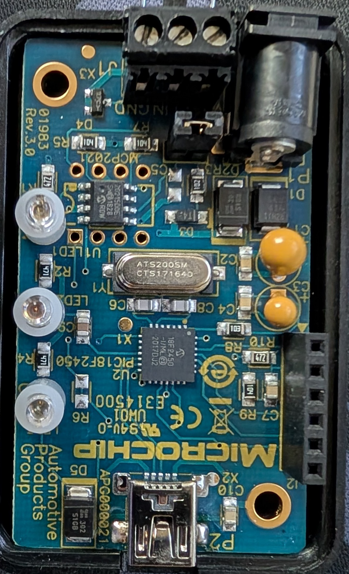
The LIN Serial Analyzer (Manufacturer Part ID: APGDT001) by Microchip is a diagnostic tool designed for monitoring, analyzing, and troubleshooting LIN (Local Interconnect Network) communication in automotive networks. It enables engineers and developers to capture LIN messages, decode them, and gain insights into the data flow and protocol compliance. This tool is essential for ensuring the reliability and performance of LIN-based systems in automotive and industrial applications.
Explore Projects Built with LIN Serial Analyzer


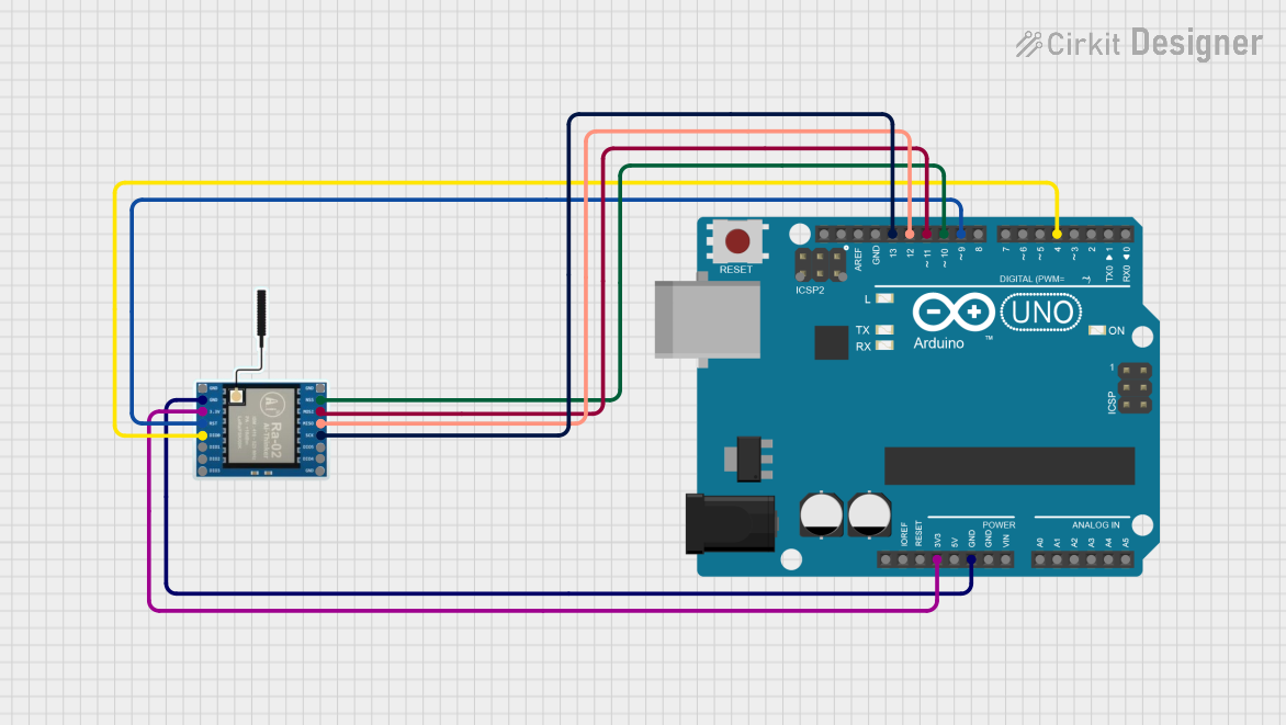
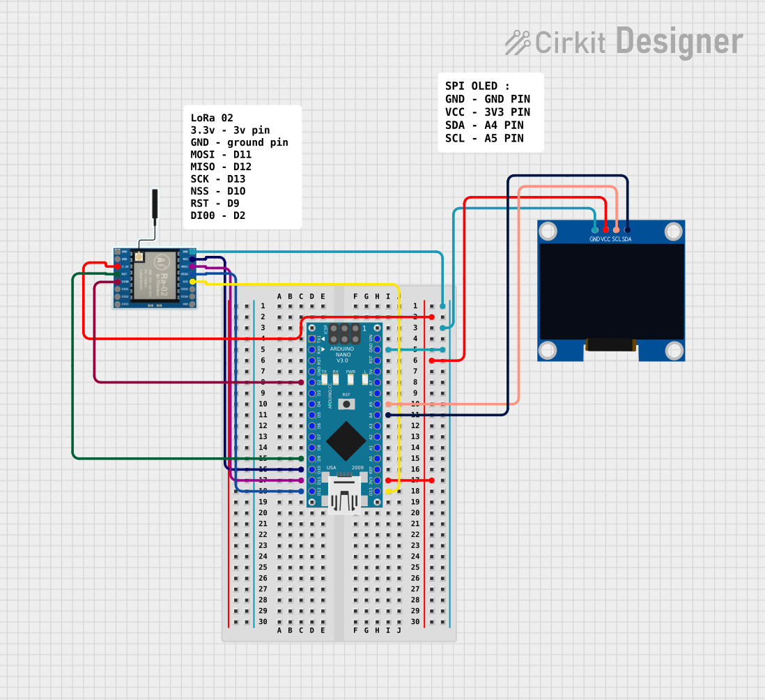
Explore Projects Built with LIN Serial Analyzer
Common Applications and Use Cases
- Automotive Systems: Debugging and validating LIN communication in vehicle subsystems such as climate control, lighting, and sensors.
- Industrial Automation: Monitoring LIN-based communication in industrial equipment.
- Embedded System Development: Testing and verifying LIN protocol compliance during development.
- Education and Research: Teaching and studying LIN communication protocols.
Technical Specifications
The following table outlines the key technical details of the LIN Serial Analyzer:
| Parameter | Specification |
|---|---|
| Manufacturer | Microchip |
| Part ID | APGDT001 |
| Communication Protocol | LIN (Local Interconnect Network) |
| LIN Protocol Version | LIN 2.0 and LIN 2.1 compliant |
| Operating Voltage | 5V (via USB interface) |
| Interface | USB 2.0 |
| Supported Baud Rates | 1 kbps to 20 kbps |
| Operating Temperature Range | -40°C to +85°C |
| Dimensions | Compact, portable design |
Pin Configuration and Descriptions
The LIN Serial Analyzer connects to a LIN bus and a host computer via USB. Below is the pin configuration for the LIN interface:
| Pin Name | Description |
|---|---|
| LIN | Connects to the LIN bus for data communication. |
| GND | Ground connection for the LIN bus. |
| USB | USB interface for power and communication with PC. |
Usage Instructions
How to Use the LIN Serial Analyzer in a Circuit
- Connect the LIN Bus:
- Attach the LIN pin of the analyzer to the LIN bus of your system.
- Connect the GND pin to the ground of the LIN bus.
- Connect to a PC:
- Use the USB interface to connect the analyzer to your computer. This provides power and enables communication with the analyzer software.
- Install Software:
- Download and install the Microchip LIN Analyzer software from the official Microchip website.
- Configure the Analyzer:
- Open the software and configure the baud rate and LIN protocol version to match your system.
- Monitor and Analyze:
- Start capturing LIN messages. The software will display decoded messages, timestamps, and other relevant data.
Important Considerations and Best Practices
- Ensure that the LIN bus voltage levels are within the specified range to avoid damage to the analyzer.
- Use a high-quality USB cable to ensure reliable communication with the PC.
- Verify that the baud rate and protocol version settings in the software match the LIN bus configuration.
- Avoid connecting the analyzer to a powered LIN bus without first connecting the GND pin to prevent potential damage.
Example: Using the LIN Serial Analyzer with Arduino UNO
The LIN Serial Analyzer can be used to monitor LIN communication in an Arduino-based project. Below is an example of Arduino code for sending LIN messages:
#include <SoftwareSerial.h>

// Define LIN TX and RX pins
#define LIN_TX 10
#define LIN_RX 11

// Initialize SoftwareSerial for LIN communication
SoftwareSerial linSerial(LIN_RX, LIN_TX);

void setup() {
  // Start serial communication for debugging
  Serial.begin(9600);
  Serial.println("LIN Serial Analyzer Example");

  // Start LIN communication
  linSerial.begin(19200); // Set baud rate to 19200 (example)
}

void loop() {
  // Send a sample LIN message
  byte linMessage[] = {0x55, 0x01, 0x02, 0x03, 0x04, 0x05, 0x06, 0x07};
  linSerial.write(linMessage, sizeof(linMessage));

  // Print message to Serial Monitor
  Serial.println("LIN message sent");

  delay(1000); // Wait 1 second before sending the next message
}
Note: The LIN Serial Analyzer will capture and decode the LIN messages sent by the Arduino. Ensure the baud rate in the Arduino code matches the analyzer's configuration.
Troubleshooting and FAQs
Common Issues and Solutions
Analyzer Not Detected by PC:
- Ensure the USB cable is securely connected.
- Verify that the required drivers are installed on your computer.
- Try using a different USB port or cable.
No LIN Messages Captured:
- Check the connections between the analyzer and the LIN bus.
- Verify that the baud rate and protocol version settings match the LIN bus configuration.
- Ensure the LIN bus is active and transmitting data.
Incorrect or Corrupted Data:
- Inspect the LIN bus for noise or interference.
- Use proper grounding to minimize electrical noise.
- Verify the integrity of the LIN bus wiring.
FAQs
Q: Can the LIN Serial Analyzer be used with LIN 1.x protocols?
A: The analyzer is designed for LIN 2.0 and 2.1. Compatibility with LIN 1.x may vary and is not guaranteed.
Q: Does the analyzer support real-time data logging?
A: Yes, the Microchip LIN Analyzer software allows real-time data capture and logging.
Q: Can I use the analyzer with a non-automotive LIN system?
A: Yes, the analyzer can be used with any LIN-based system, provided the voltage levels and protocol settings are compatible.
Q: Is the analyzer compatible with Linux or macOS?
A: The official software is primarily designed for Windows. For other operating systems, additional configuration or third-party tools may be required.
By following this documentation, users can effectively utilize the LIN Serial Analyzer for their LIN communication projects.