How to Use LX LCBST: Examples, Pinouts, and Specs
Introduction
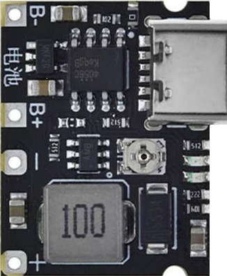
The LX LCBST is a low-cost, high-performance linear current booster designed to enhance the output current of a circuit. It is particularly useful for driving loads that require higher current levels than the primary power source can provide. The component is commonly used in solar power systems, motor control circuits, and other applications where efficient current boosting is essential.
Explore Projects Built with LX LCBST


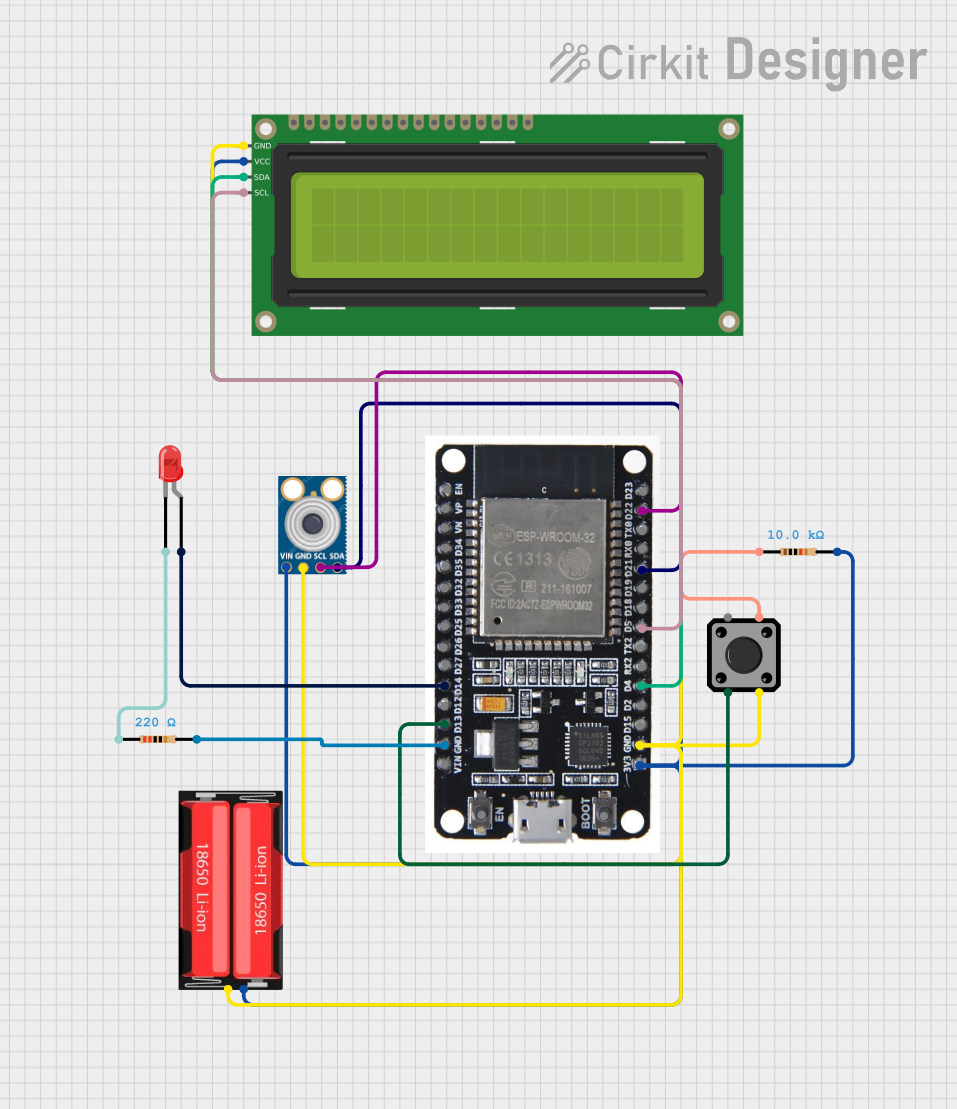
Explore Projects Built with LX LCBST
Common Applications and Use Cases
- Solar panel systems to drive motors or pumps
- Battery-powered devices requiring higher current output
- Motor control circuits for robotics and automation
- LED lighting systems with high current demands
Technical Specifications
The LX LCBST is designed to operate efficiently in a variety of environments. Below are its key technical specifications:
| Parameter | Value |
|---|---|
| Input Voltage Range | 6V to 24V |
| Output Current | Up to 10A |
| Efficiency | Up to 95% |
| Operating Temperature | -40°C to +85°C |
| Quiescent Current | < 10mA |
| Package Type | TO-220 or DIP-8 |
Pin Configuration and Descriptions
The LX LCBST typically comes in a TO-220 package with the following pinout:
| Pin Number | Pin Name | Description |
|---|---|---|
| 1 | VIN | Input voltage pin. Connect to the power source. |
| 2 | GND | Ground pin. Connect to the circuit ground. |
| 3 | VOUT | Output voltage pin. Connect to the load. |
| 4 | ENABLE | Enable pin. High to enable the booster, low to disable. |
| 5 | FB | Feedback pin. Used for voltage regulation. |
Usage Instructions
The LX LCBST is straightforward to use in a circuit. Follow these steps to integrate it effectively:
Connect the Input Voltage (VIN):
- Ensure the input voltage is within the specified range (6V to 24V).
- Connect the VIN pin to the positive terminal of the power source.
Connect the Ground (GND):
- Connect the GND pin to the circuit ground.
Connect the Output Voltage (VOUT):
- Attach the VOUT pin to the load requiring boosted current.
Enable the Booster:
- Use the ENABLE pin to control the booster. Apply a high signal (logic 1) to enable the component.
Feedback Configuration:
- Use the FB pin to set the desired output voltage. This is typically done with a resistor divider network.
Important Considerations and Best Practices
- Heat Dissipation: The LX LCBST can generate heat during operation. Use an appropriate heatsink if the current exceeds 5A.
- Input Voltage: Ensure the input voltage is stable and within the specified range to avoid damage.
- Capacitor Selection: Place a low ESR capacitor (e.g., 100µF) near the VIN and VOUT pins to stabilize the circuit.
- Enable Pin: If the ENABLE pin is not used, connect it to VIN to keep the booster always active.
Example: Using LX LCBST with Arduino UNO
The LX LCBST can be used with an Arduino UNO to drive a motor requiring higher current. Below is an example circuit and code:
Circuit Setup
- Connect the Arduino's 5V pin to the ENABLE pin of the LX LCBST.
- Connect the motor to the VOUT pin of the LX LCBST.
- Connect the VIN pin of the LX LCBST to a 12V power source.
Arduino Code
// Example code to control the LX LCBST with an Arduino UNO
// This code enables and disables the booster to control a motor.

const int enablePin = 7; // Pin connected to the ENABLE pin of LX LCBST

void setup() {
  pinMode(enablePin, OUTPUT); // Set the enable pin as an output
  digitalWrite(enablePin, LOW); // Start with the booster disabled
}

void loop() {
  // Enable the booster to power the motor
  digitalWrite(enablePin, HIGH);
  delay(5000); // Keep the motor running for 5 seconds

  // Disable the booster to stop the motor
  digitalWrite(enablePin, LOW);
  delay(5000); // Wait for 5 seconds before restarting
}
Troubleshooting and FAQs
Common Issues and Solutions
No Output Current:
- Cause: The ENABLE pin is not connected or set to LOW.
- Solution: Ensure the ENABLE pin is connected to a HIGH signal or VIN.
Overheating:
- Cause: Excessive current draw or insufficient heat dissipation.
- Solution: Use a heatsink and ensure the current does not exceed 10A.
Unstable Output Voltage:
- Cause: Insufficient input capacitance or incorrect feedback configuration.
- Solution: Add a low ESR capacitor near the VIN and VOUT pins. Verify the resistor divider network on the FB pin.
Component Not Working:
- Cause: Input voltage is out of range.
- Solution: Verify that the input voltage is between 6V and 24V.
FAQs
Q1: Can the LX LCBST be used with a 5V input?
A1: No, the minimum input voltage is 6V. Using a 5V input may result in improper operation or damage.
Q2: What is the maximum load the LX LCBST can drive?
A2: The LX LCBST can drive loads up to 10A, provided proper heat dissipation is ensured.
Q3: Can I leave the ENABLE pin floating?
A3: No, the ENABLE pin must be connected to either a HIGH signal or VIN to activate the booster.
Q4: Is the LX LCBST suitable for battery-powered applications?
A4: Yes, it is ideal for battery-powered systems where current boosting is required, as long as the input voltage is within range.
By following this documentation, users can effectively integrate the LX LCBST into their projects and troubleshoot common issues with ease.