
How to Use AirValve: Examples, Pinouts, and Specs
 Design with AirValve in Cirkit Designer
Introduction
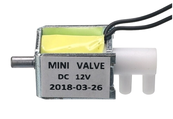
The 12V AirValve is an electronic device designed to control the flow of air in pneumatic systems. By regulating airflow, it enables precise control of pressure and movement in a variety of applications. This component is commonly used in automation systems, robotics, HVAC systems, and industrial machinery. Its compact design and 12V operation make it suitable for integration into low-power systems.
Explore Projects Built with AirValve
 Open Project in Cirkit Designer
 Open Project in Cirkit Designer
 Open Project in Cirkit Designer
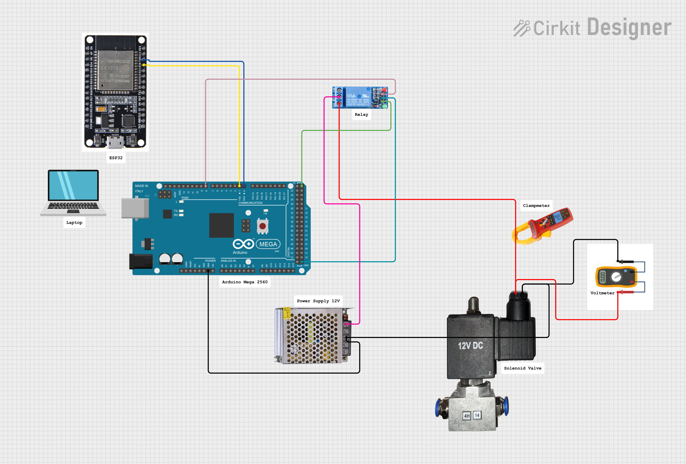 Open Project in Cirkit Designer
Explore Projects Built with AirValve
Open Project in Cirkit DesignerOpen Project in Cirkit DesignerOpen Project in Cirkit DesignerOpen Project in Cirkit DesignerCommon Applications
- Pneumatic actuators in industrial automation
- Airflow control in HVAC systems
- Robotics for controlling pneumatic grippers or actuators
- Medical devices requiring regulated air pressure
- Automotive systems, such as air suspension or intake control
Technical Specifications
Below are the key technical details for the 12V AirValve:
| Parameter | Value |
|---|---|
| Operating Voltage | 12V DC |
| Operating Current | 200 mA (typical) |
| Maximum Pressure | 100 PSI |
| Response Time | < 20 ms |
| Port Size | 1/8" NPT |
| Material | Brass and plastic components |
| Operating Temperature | -10°C to 50°C |
| Weight | 150 grams |
Pin Configuration
The 12V AirValve typically has two electrical connections for operation. These are described in the table below:
| Pin | Label | Description |
|---|---|---|
| 1 | V+ | Positive terminal for 12V DC power supply |
| 2 | GND | Ground terminal for the power supply |
Usage Instructions
How to Use the AirValve in a Circuit
- Power Supply: Connect the positive terminal of a 12V DC power supply to the V+ pin of the AirValve. Connect the negative terminal of the power supply to the GND pin.
- Control Signal: Use a switch, relay, or microcontroller (e.g., Arduino) to control the power to the AirValve. When power is applied, the valve opens to allow airflow; when power is removed, the valve closes.
- Pneumatic Connections: Attach the air input and output hoses to the valve's ports. Ensure the connections are secure to prevent air leaks.
- Testing: Apply power to the valve and verify that it opens and closes as expected. Check for proper airflow and ensure there are no leaks.
Important Considerations
- Voltage Compatibility: Ensure the power supply provides a stable 12V DC output. Using a higher voltage may damage the valve.
- Current Requirements: Verify that the power source can supply at least 200 mA of current.
- Air Pressure: Do not exceed the maximum pressure rating of 100 PSI to avoid damaging the valve.
- Orientation: Install the valve in the correct orientation as indicated by the airflow direction markings on the body.
- Noise Suppression: If using the valve with a microcontroller, consider adding a flyback diode across the terminals to suppress voltage spikes caused by the inductive load.
Example: Connecting the AirValve to an Arduino UNO
Below is an example of how to control the 12V AirValve using an Arduino UNO and a relay module:
Circuit Diagram
- Connect the V+ pin of the AirValve to the NO (Normally Open) terminal of the relay.
- Connect the GND pin of the AirValve to the GND of the power supply.
- Connect the COM (Common) terminal of the relay to the positive terminal of the 12V power supply.
- Connect the relay module's control pin to an Arduino digital pin (e.g., pin 7).
Arduino Code
// Define the pin connected to the relay module
const int relayPin = 7;

void setup() {
  pinMode(relayPin, OUTPUT); // Set the relay pin as an output
  digitalWrite(relayPin, LOW); // Ensure the relay is off at startup
}

void loop() {
  // Turn the AirValve on
  digitalWrite(relayPin, HIGH); // Activate the relay
  delay(5000); // Keep the valve open for 5 seconds

  // Turn the AirValve off
  digitalWrite(relayPin, LOW); // Deactivate the relay
  delay(5000); // Keep the valve closed for 5 seconds
}
Notes:
- Use a relay module that can handle the 12V AirValve's current requirements.
- Add a flyback diode across the AirValve terminals to protect the relay and Arduino from voltage spikes.
Troubleshooting and FAQs
Common Issues and Solutions
| Issue | Possible Cause | Solution |
|---|---|---|
| Valve does not open or close | Insufficient power supply | Ensure the power supply provides 12V and 200 mA. |
| Air leaks from the valve | Loose or improperly connected hoses | Check and tighten all pneumatic connections. |
| Valve operates intermittently | Voltage spikes or noise in the circuit | Add a flyback diode across the valve terminals. |
| Arduino cannot control the valve | Incorrect relay wiring or code issues | Verify the relay connections and Arduino code. |
| Overheating of the valve | Exceeding the duty cycle or pressure rating | Operate within the specified limits. |
FAQs
Can I use the AirValve with a 24V power supply?
- No, the AirValve is designed for 12V DC operation. Using a higher voltage may damage the component.
What type of hoses should I use with the valve?
- Use hoses compatible with 1/8" NPT ports and rated for pressures up to 100 PSI.
Can the AirValve be used in outdoor environments?
- The valve is not weatherproof. If used outdoors, ensure it is protected from moisture and extreme temperatures.
How do I reduce noise when switching the valve?
- Install a flyback diode across the valve terminals and use a capacitor to filter noise in the power supply.
By following this documentation, you can effectively integrate the 12V AirValve into your pneumatic systems and troubleshoot common issues.