How to Use Transformer: Examples, Pinouts, and Specs
Introduction
A transformer is an electrical device that transfers electrical energy between two or more circuits through electromagnetic induction. It is primarily used to increase (step-up) or decrease (step-down) voltage levels in power systems. Transformers are essential in electrical power distribution, enabling efficient transmission of electricity over long distances and ensuring compatibility between different voltage levels in various applications.
Explore Projects Built with Transformer


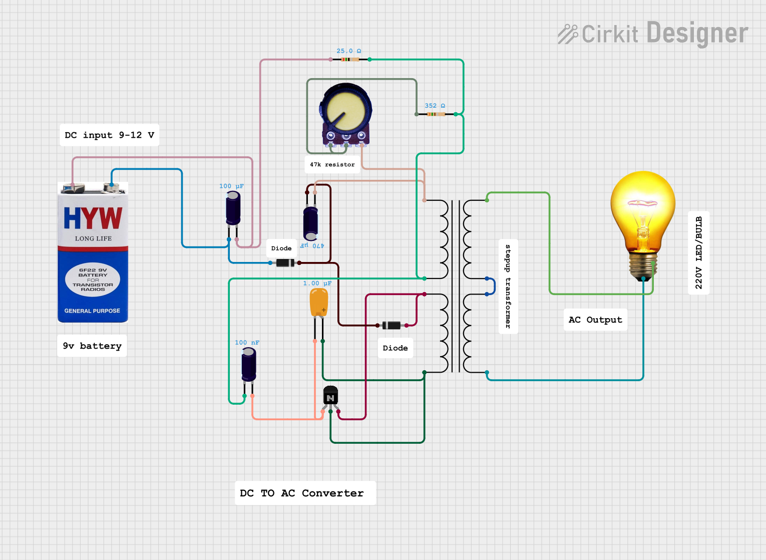
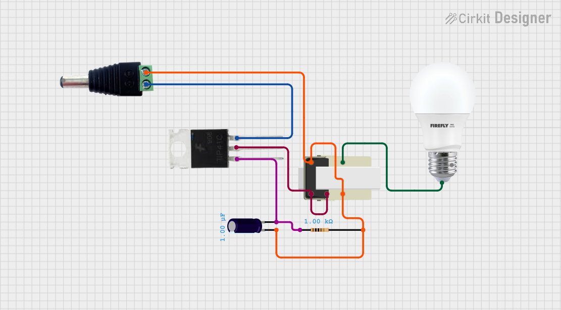
Explore Projects Built with Transformer
Common Applications and Use Cases
- Power distribution in electrical grids
- Voltage regulation in electronic devices
- Isolation between circuits for safety
- Impedance matching in audio systems
- Use in power supplies for converting AC voltage levels
Technical Specifications
Transformers come in various types and sizes, but the following are general technical specifications for a typical transformer:
Key Technical Details
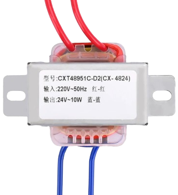
- Input Voltage (Primary): Varies depending on the design (e.g., 110V, 220V AC)
- Output Voltage (Secondary): Varies depending on the application (e.g., 12V, 24V AC)
- Frequency: Typically 50Hz or 60Hz
- Power Rating: Ranges from milliwatts (small transformers) to megawatts (power transformers)
- Efficiency: Typically 95% or higher for large transformers
- Insulation Class: Determines the maximum operating temperature (e.g., Class A, B, F, H)
Pin Configuration and Descriptions
The pin configuration of a transformer depends on its type (e.g., step-up, step-down, or isolation transformer). Below is a general example of a transformer with a primary and secondary winding:
| Pin Number | Name | Description |
|---|---|---|
| 1 | Primary Winding 1 | First terminal of the primary winding (input) |
| 2 | Primary Winding 2 | Second terminal of the primary winding (input) |
| 3 | Secondary Winding 1 | First terminal of the secondary winding (output) |
| 4 | Secondary Winding 2 | Second terminal of the secondary winding (output) |
For center-tapped transformers, an additional pin is provided for the center tap on the secondary winding.
| Pin Number | Name | Description |
|---|---|---|
| 5 | Center Tap | Midpoint of the secondary winding (optional) |
Usage Instructions
How to Use the Component in a Circuit
Determine Voltage Requirements:
- Identify the input voltage (primary) and the desired output voltage (secondary) for your application.
- Select a transformer with the appropriate voltage ratings.
Connect the Primary Winding:
- Connect the primary winding terminals (e.g., Pin 1 and Pin 2) to the AC power source.
- Ensure the input voltage matches the transformer's primary voltage rating.
Connect the Secondary Winding:
- Connect the secondary winding terminals (e.g., Pin 3 and Pin 4) to the load or circuit requiring the output voltage.
- If using a center-tapped transformer, connect the center tap (Pin 5) as needed.
Safety Precautions:
- Ensure proper insulation and grounding to prevent electrical hazards.
- Avoid overloading the transformer beyond its power rating.
Important Considerations and Best Practices
- Efficiency: Use transformers with high efficiency to minimize energy losses.
- Heat Dissipation: Ensure adequate ventilation or cooling to prevent overheating.
- Frequency Compatibility: Verify that the transformer is designed for the operating frequency (50Hz or 60Hz).
- Isolation: Use isolation transformers for safety-critical applications to separate the primary and secondary circuits.
Example: Using a Transformer with an Arduino UNO
If you are using a transformer to power an Arduino UNO, you will typically need a step-down transformer to reduce the AC voltage to a level suitable for the Arduino's power supply. Below is an example of how to use a transformer with a rectifier circuit to provide DC voltage:
/* Example: Using a transformer to power an Arduino UNO
   This example assumes a step-down transformer is used to convert 220V AC to 12V AC.
   A rectifier and voltage regulator are required to convert 12V AC to 5V DC.
*/

// Connect the transformer's primary winding to the AC mains (e.g., 220V AC).
// Use a bridge rectifier to convert the transformer's 12V AC output to DC.
// Add a capacitor (e.g., 1000uF) to smooth the DC voltage.
// Use a 7805 voltage regulator to provide a stable 5V DC output for the Arduino UNO.

// Note: Ensure proper insulation and safety precautions when working with AC voltage.
Troubleshooting and FAQs
Common Issues Users Might Face
Transformer Overheating:
- Cause: Overloading or insufficient ventilation.
- Solution: Reduce the load or improve cooling and ventilation.
No Output Voltage:
- Cause: Incorrect wiring or a damaged winding.
- Solution: Verify connections and check the winding continuity with a multimeter.
Humming Noise:
- Cause: Loose laminations or excessive magnetizing current.
- Solution: Tighten the core laminations or use a transformer with better design.
Voltage Drop Under Load:
- Cause: Transformer is undersized for the load.
- Solution: Use a transformer with a higher power rating.
Solutions and Tips for Troubleshooting
- Use a multimeter to measure input and output voltages.
- Check for proper grounding and insulation to avoid short circuits.
- Inspect the transformer for physical damage or signs of overheating.
- Ensure the input voltage matches the transformer's primary voltage rating.
By following these guidelines, you can effectively use and troubleshoot transformers in your electronic projects.