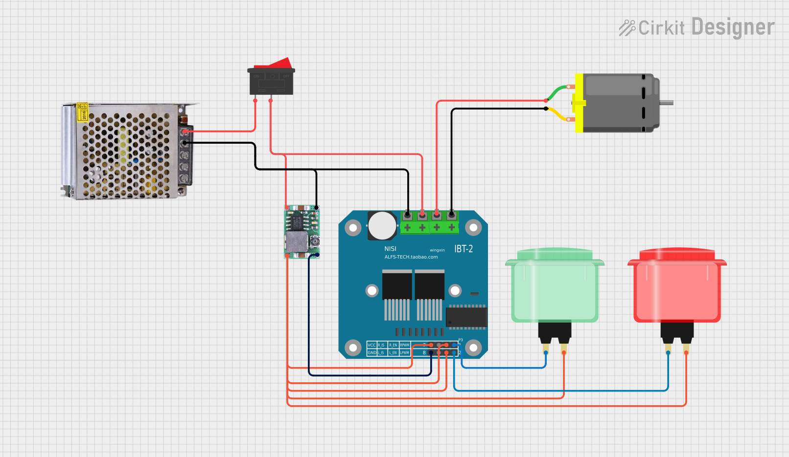
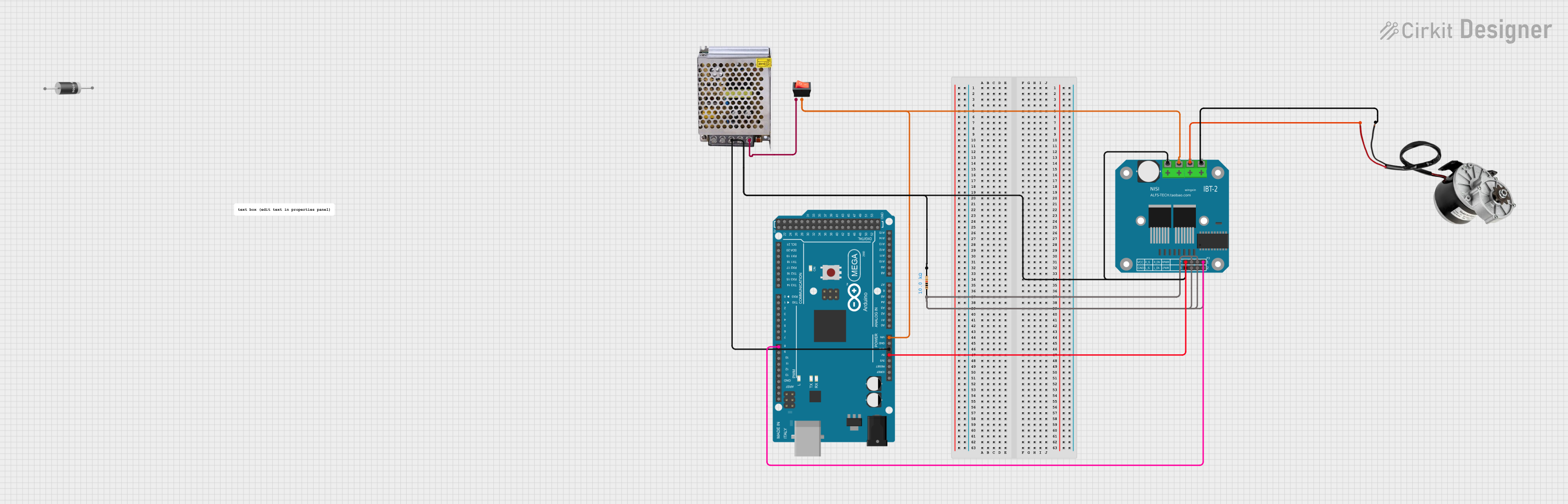
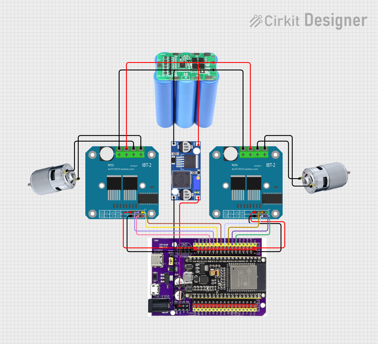
Introduction
The BTS7960 is a robust and efficient motor driver module designed to control DC motors with high current requirements, supporting up to 43A. It features an H-Bridge configuration, enabling bidirectional motor control. This module is ideal for applications requiring precise motor control, such as robotics, electric vehicles, conveyor systems, and industrial automation.
The BTS7960 integrates overcurrent protection, overtemperature protection, and a high-power MOSFET design, ensuring reliable operation under demanding conditions. Its compatibility with microcontrollers like Arduino, Raspberry Pi, and other development boards makes it a versatile choice for hobbyists and professionals alike.
Technical Specifications
- Operating Voltage (Vcc): 5V (logic level)
- Motor Voltage (VM): 6V to 27V
- Maximum Continuous Current: 43A
- Control Logic Voltage: 3.3V or 5V (compatible with most microcontrollers)
- PWM Frequency: Up to 25kHz
- Overcurrent Protection: Yes
- Overtemperature Protection: Yes
- Dimensions: 43mm x 45mm x 28mm (approx.)
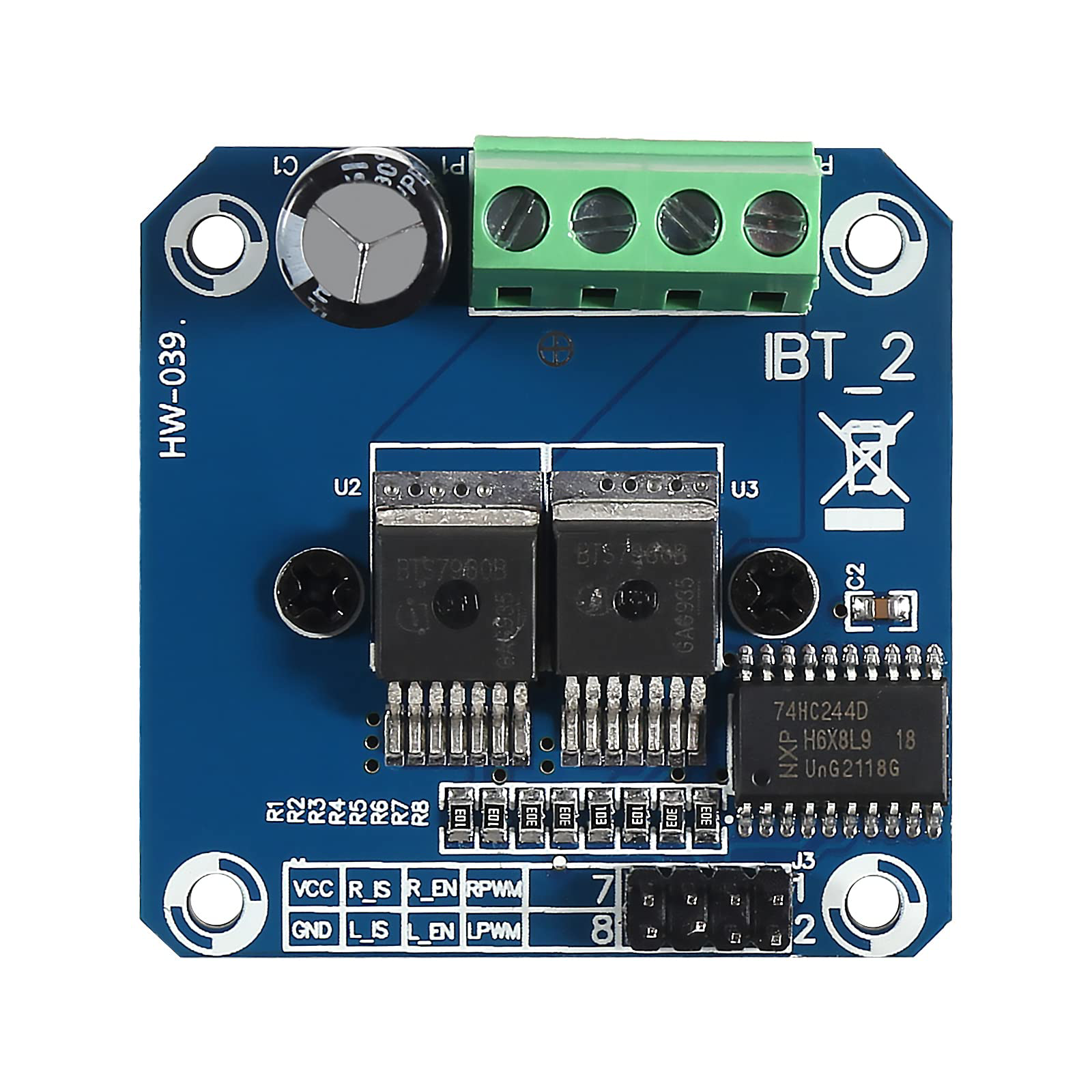
Pin Configuration and Descriptions
The BTS7960 module has multiple pins for power, control, and motor connections. Below is a detailed description:
Usage Instructions
How to Use the BTS7960 in a Circuit
Power Connections:
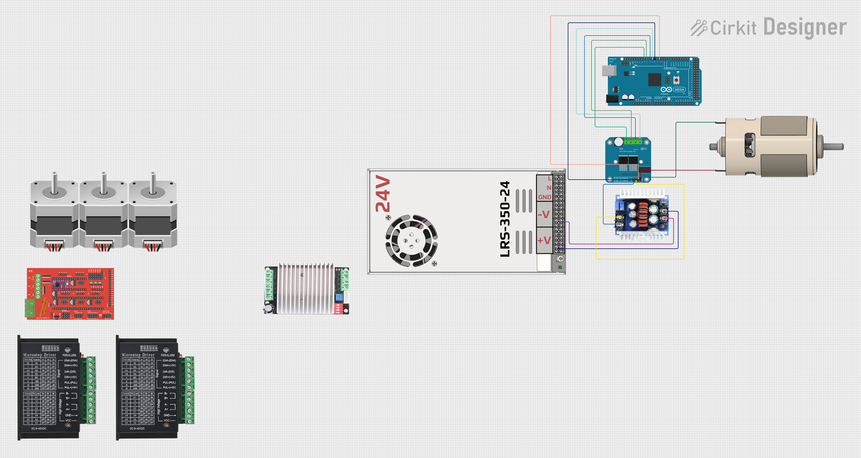
- Connect the motor power supply (6V to 27V) to the
B+ pin and ground to the B- pin.
- Connect the logic power supply (5V) to the
VCC pin and ground to the GND pin.
Motor Connections:
- Connect the motor terminals to the
M+ and M- pins.
Control Connections:
- Connect the
ENA and ENB pins to the microcontroller's GPIO pins to enable or disable the motor.
- Use the
IN1 and IN2 pins to control the motor's direction.
- Connect the
RPWM and LPWM pins to the microcontroller's PWM output pins for speed control.
Programming:
- Use a microcontroller (e.g., Arduino UNO) to send PWM signals and control the motor's speed and direction.
Important Considerations and Best Practices
- Ensure the motor's current rating does not exceed 43A to avoid damaging the module.
- Use a heat sink or cooling fan for prolonged high-current operation.
- Add a capacitor (e.g., 1000µF) across the motor power supply terminals to reduce voltage spikes.
- Avoid reversing the polarity of the power supply or motor connections.
- Use appropriate fuses or circuit breakers for additional protection.
Example Arduino Code
Below is an example code to control a DC motor using the BTS7960 and an Arduino UNO:
// Define control pins for the BTS7960
#define ENA 7    // Enable pin for motor A
#define ENB 8    // Enable pin for motor B
#define RPWM 9   // PWM pin for motor A
#define LPWM 10  // PWM pin for motor B

void setup() {
  // Set control pins as outputs
  pinMode(ENA, OUTPUT);
  pinMode(ENB, OUTPUT);
  pinMode(RPWM, OUTPUT);
  pinMode(LPWM, OUTPUT);

  // Enable the motor driver
  digitalWrite(ENA, HIGH);
  digitalWrite(ENB, HIGH);
}

void loop() {
  // Rotate motor in one direction
  analogWrite(RPWM, 128); // Set speed (0-255)
  analogWrite(LPWM, 0);   // Stop the other direction
  delay(2000);            // Run for 2 seconds

  // Rotate motor in the opposite direction
  analogWrite(RPWM, 0);   // Stop one direction
  analogWrite(LPWM, 128); // Set speed (0-255)
  delay(2000);            // Run for 2 seconds
}
Troubleshooting and FAQs
Common Issues and Solutions
Motor Not Running:
- Ensure the
ENA and ENB pins are set to HIGH.
- Verify the motor power supply voltage is within the specified range (6V to 27V).
- Check all connections for loose wires or incorrect polarity.
Overheating:
- Use a heat sink or cooling fan to dissipate heat during high-current operation.
- Ensure the motor's current rating does not exceed 43A.
PWM Signal Not Working:
- Verify the PWM frequency is within the supported range (up to 25kHz).
- Check the microcontroller's PWM pin configuration and ensure it is functioning correctly.
Motor Running in the Wrong Direction:
- Swap the
IN1 and IN2 signals or reverse the motor connections (M+ and M-).
FAQs
Can I use the BTS7960 with a 3.3V microcontroller?
Yes, the BTS7960 is compatible with both 3.3V and 5V logic levels.
What is the maximum PWM frequency supported?
The BTS7960 supports PWM frequencies up to 25kHz.
Do I need additional components for protection?
While the BTS7960 has built-in protection, adding a capacitor across the motor power supply and a fuse can enhance safety and reliability.
Can I control two motors with one BTS7960 module?
No, the BTS7960 is designed to control a single motor. For dual-motor control, use two separate modules.

 Open Project in Cirkit Designer