
How to Use Easier Lamp (RED): Examples, Pinouts, and Specs
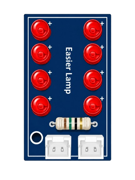
 Design with Easier Lamp (RED) in Cirkit Designer
Introduction
The Easier Lamp (RED) is a simple LED lamp that emits bright red light. It is commonly used as an indicator in electronic circuits, decorative lighting, or as part of DIY projects. Its compact size, low power consumption, and ease of use make it a popular choice for hobbyists and professionals alike.
Explore Projects Built with Easier Lamp (RED)
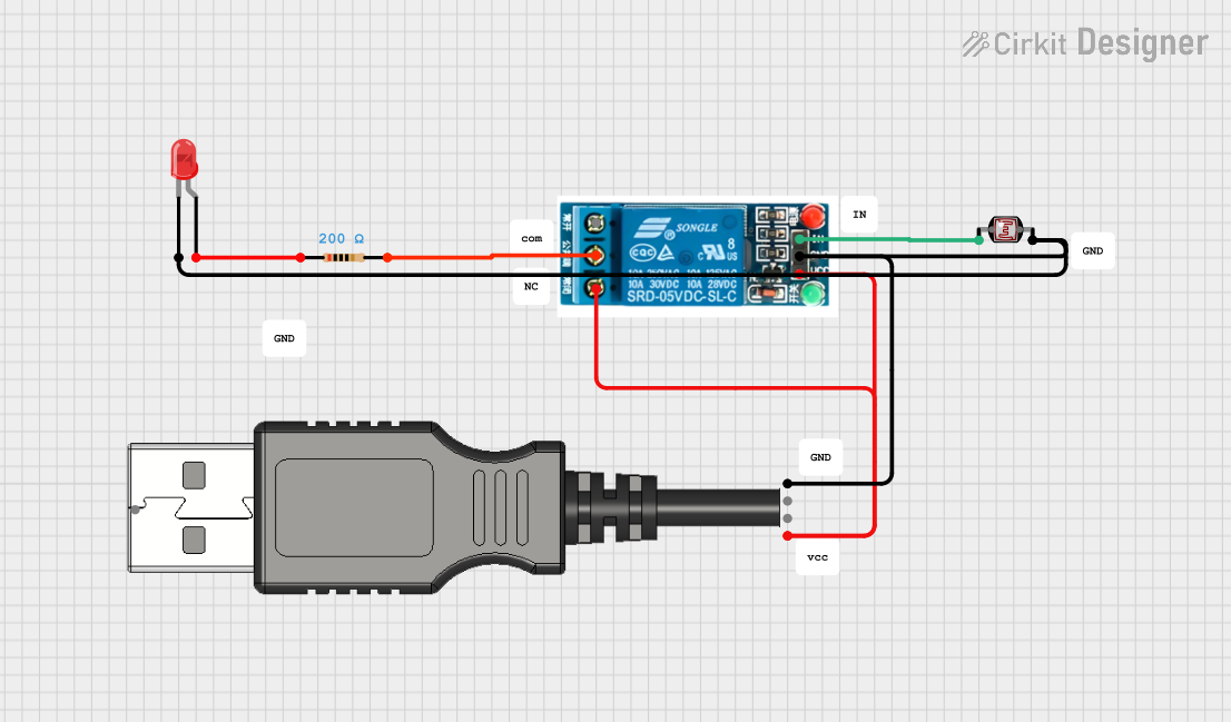 Open Project in Cirkit Designer
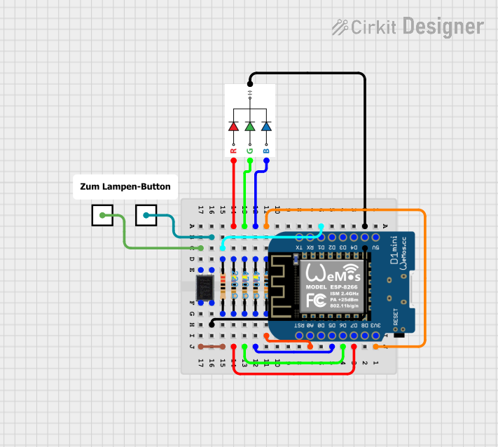 Open Project in Cirkit Designer
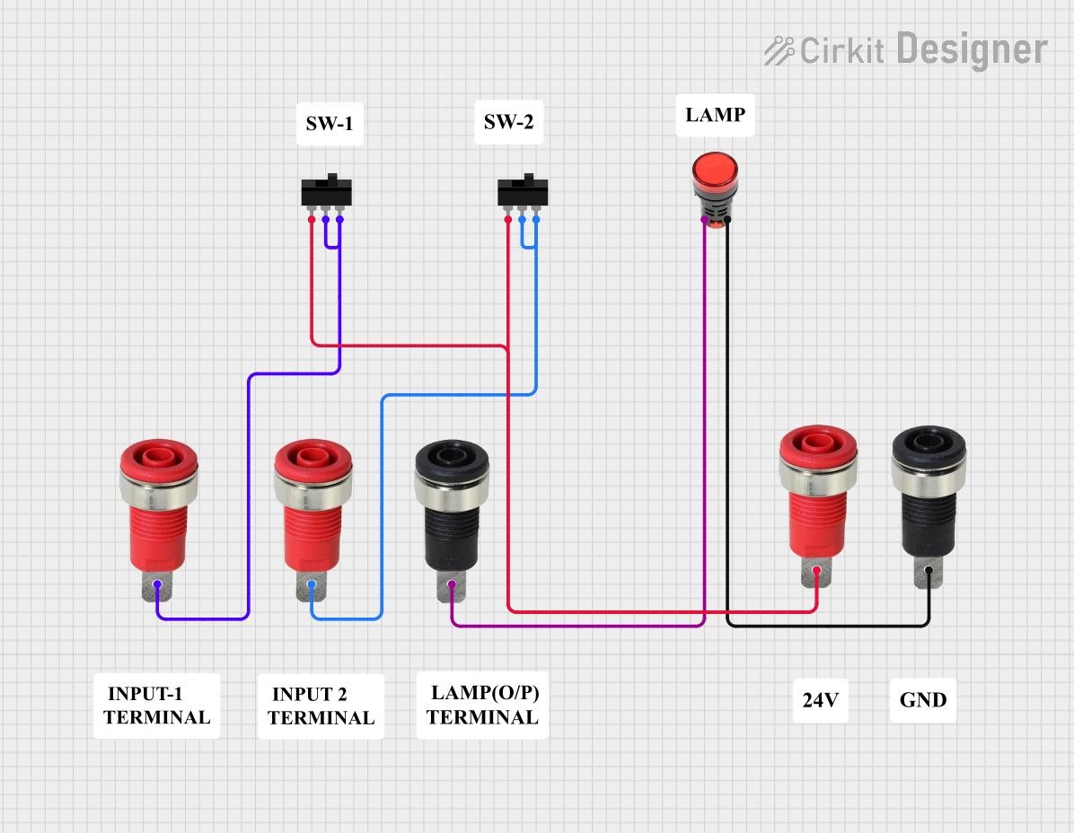 Open Project in Cirkit Designer
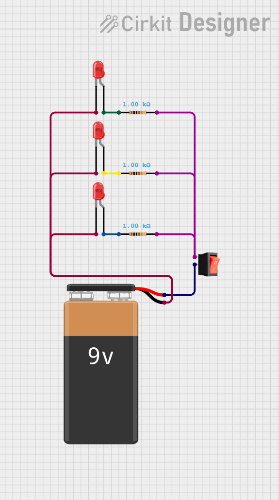 Open Project in Cirkit Designer
Explore Projects Built with Easier Lamp (RED)
Open Project in Cirkit DesignerOpen Project in Cirkit DesignerOpen Project in Cirkit DesignerOpen Project in Cirkit DesignerTechnical Specifications
- Type: Red LED Lamp
- Forward Voltage: 1.8V to 2.2V
- Forward Current: 20mA (typical)
- Power Dissipation: 50mW (maximum)
- Viewing Angle: 30° to 60° (varies by model)
- Wavelength: 620nm to 630nm (red light spectrum)
- Polarity: Anode (+) and Cathode (-)
Pin Configuration and Descriptions
The Easier Lamp (RED) has two pins:
| Pin Name | Description | Identification Method |
|---|---|---|
| Anode | Positive terminal (+) | Longer leg of the LED |
| Cathode | Negative terminal (-) | Shorter leg of the LED or flat |
| edge on the LED casing |
Usage Instructions
How to Use the Easier Lamp (RED) in a Circuit
Determine the Resistor Value: To prevent damage to the LED, always use a current-limiting resistor in series with the LED. Use the formula: [ R = \frac{V_{supply} - V_{forward}}{I_{forward}} ]
- (V_{supply}): Supply voltage
- (V_{forward}): Forward voltage of the LED (1.8V to 2.2V)
- (I_{forward}): Desired forward current (typically 20mA)
For example, if (V_{supply} = 5V) and (V_{forward} = 2V), the resistor value is: [ R = \frac{5V - 2V}{0.02A} = 150\Omega ]
Connect the LED:
- Connect the anode (longer leg) to the positive terminal of the power supply through the resistor.
- Connect the cathode (shorter leg) to the ground.
Power the Circuit: Apply the appropriate voltage to the circuit. The LED will emit red light.
Important Considerations and Best Practices
- Polarity Matters: Ensure the anode and cathode are connected correctly. Reversing the polarity may damage the LED.
- Avoid Overcurrent: Always use a resistor to limit the current. Exceeding the maximum forward current (20mA) can permanently damage the LED.
- Heat Management: While the Easier Lamp (RED) generates minimal heat, ensure proper ventilation in high-density circuits.
Example: Connecting to an Arduino UNO
The Easier Lamp (RED) can be easily controlled using an Arduino UNO. Below is an example of how to blink the LED:
Circuit Setup
- Connect the anode of the LED to digital pin 13 on the Arduino through a 220Ω resistor.
- Connect the cathode to the Arduino's GND pin.
Arduino Code
// Blink the Easier Lamp (RED) using Arduino UNO
// Connect the LED anode to pin 13 through a 220Ω resistor
// Connect the LED cathode to GND

void setup() {
  pinMode(13, OUTPUT); // Set pin 13 as an output
}

void loop() {
  digitalWrite(13, HIGH); // Turn the LED on
  delay(1000);            // Wait for 1 second
  digitalWrite(13, LOW);  // Turn the LED off
  delay(1000);            // Wait for 1 second
}
Troubleshooting and FAQs
Common Issues
LED Does Not Light Up:
Cause: Incorrect polarity.
Solution: Ensure the anode is connected to the positive terminal and the cathode to ground.
Cause: No current-limiting resistor or incorrect resistor value.
Solution: Verify the resistor value using the formula provided above.
LED Flickers or is Dim:
- Cause: Insufficient current or unstable power supply.
- Solution: Check the power supply voltage and ensure the resistor value is appropriate.
LED Burns Out Quickly:
- Cause: Excessive current.
- Solution: Use a resistor to limit the current to 20mA or less.
FAQs
Can I use the Easier Lamp (RED) without a resistor? No, using the LED without a resistor can cause it to draw excessive current, leading to permanent damage.
What is the maximum voltage I can apply to the LED? The LED itself has a forward voltage of 1.8V to 2.2V. Any voltage higher than this must be paired with a current-limiting resistor.
Can I use the Easier Lamp (RED) with a 3.3V or 5V microcontroller? Yes, but you must calculate and use an appropriate resistor to limit the current.
How do I identify the anode and cathode if the legs are trimmed? Look for the flat edge on the LED casing, which indicates the cathode (-). The other side is the anode (+).