How to Use USB C PD Trigger Board: Examples, Pinouts, and Specs
Introduction
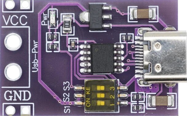
The USB C PD Trigger Board is an electronic component designed to facilitate power delivery negotiation over USB-C connections. This board is essential for projects that require precise control over the power supplied to devices via USB-C, which is becoming the standard for charging and data transfer across a wide range of devices. Common applications include custom chargers, battery-powered projects, and any system that needs to dynamically adjust power supply from a USB-C source.
Explore Projects Built with USB C PD Trigger Board
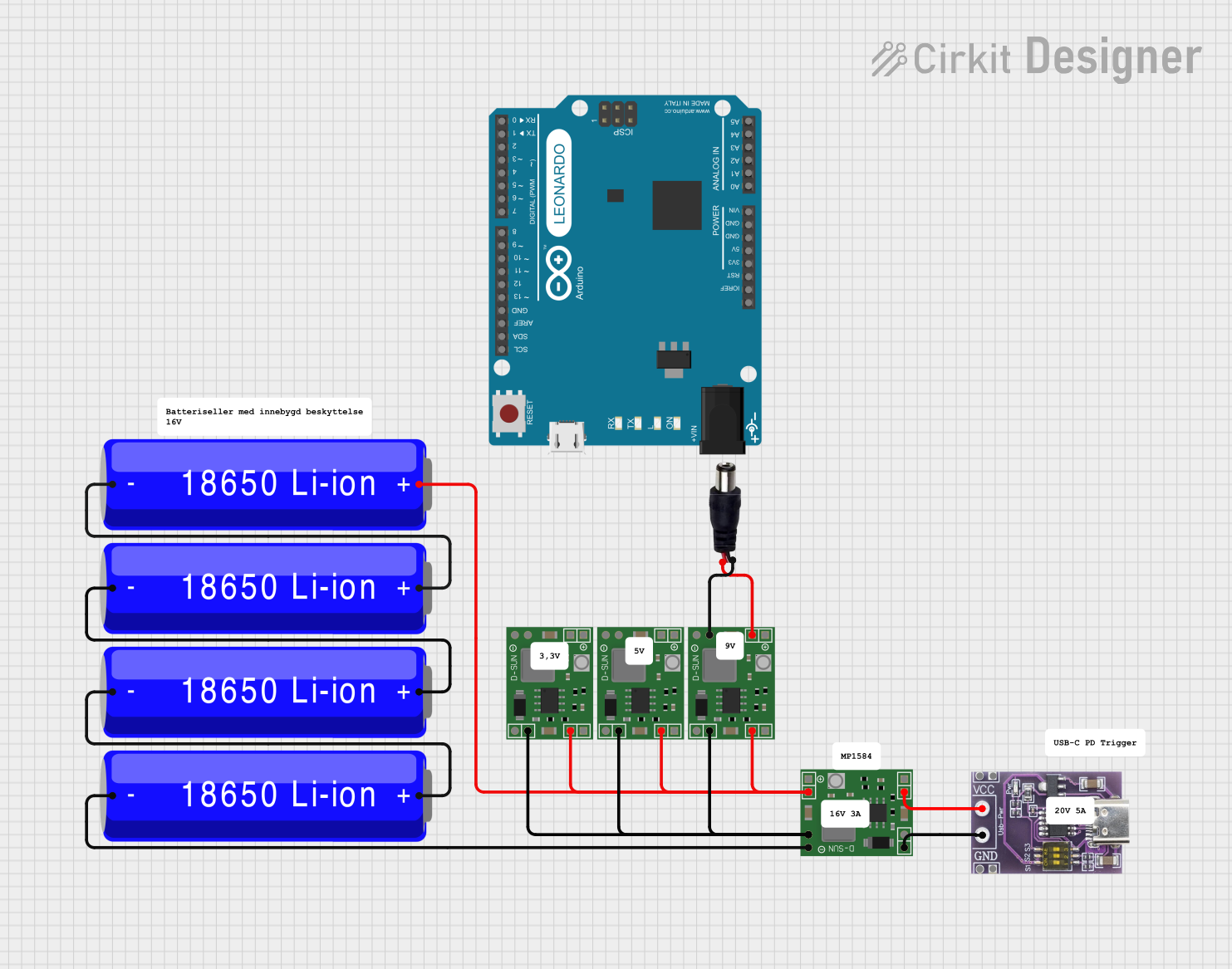


Explore Projects Built with USB C PD Trigger Board
Technical Specifications
Key Technical Details
- Input Voltage: Typically 5V to 20V (varies by model)
- Output Voltage: Configurable via PD negotiation
- Maximum Current: Depends on the negotiated power profile
- Power Delivery Profiles: Supports multiple PD profiles for compatibility with various devices
- Communication Interface: I2C or UART (model dependent)
- Operating Temperature: -40°C to +85°C (industrial grade components)
Pin Configuration and Descriptions
| Pin Number | Pin Name | Description |
|---|---|---|
| 1 | VBUS | Connected to the USB-C VBUS line |
| 2 | GND | Ground connection |
| 3 | SCL | I2C clock line (if I2C interface is used) |
| 4 | SDA | I2C data line (if I2C interface is used) |
| 5 | TX | UART transmit line (if UART interface is used) |
| 6 | RX | UART receive line (if UART interface is used) |
| 7 | CONFIG | Configuration pin (used to set PD profiles) |
| 8 | FLAG | Indicates the status of PD negotiation |
Usage Instructions
How to Use the Component in a Circuit
- Power Connections: Connect the VBUS pin to the positive line of your USB-C power source and the GND pin to the common ground.
- Data Connections: Depending on the model, connect the SCL and SDA pins for I2C communication or TX and RX for UART communication to your microcontroller.
- Configuration: Use the CONFIG pin to select the desired power delivery profile according to the board's datasheet.
- Status Monitoring: Monitor the FLAG pin to determine the status of the power delivery negotiation.
Important Considerations and Best Practices
- Ensure that the power source can supply the maximum current that the board might negotiate.
- Use pull-up resistors on the I2C lines if they are not built into the board.
- Protect the board from electrostatic discharge (ESD) during handling.
- Verify that the USB-C cable used is capable of supporting the negotiated power delivery profile.
Troubleshooting and FAQs
Common Issues
- Power Delivery Not Triggering: Ensure that the CONFIG pin is set correctly and that the power source supports USB PD.
- Communication Errors: Check the integrity of the I2C or UART connections and confirm that the correct communication protocol is being used.
- Overheating: If the board gets too hot, ensure that the negotiated power does not exceed the board's specifications.
Solutions and Tips for Troubleshooting
- Double-check wiring, especially the VBUS and GND connections.
- Use a USB-C power source with a known power delivery capability.
- If using I2C, ensure that the address conflicts are resolved and that the bus is not overloaded.
FAQs
Q: Can I use this board to negotiate power delivery for any USB-C device? A: Yes, as long as the device supports USB PD and the board is configured for the correct power profile.
Q: What should I do if the device does not start charging? A: Verify the power source, check the CONFIG pin setting, and ensure the USB-C cable is fully inserted and supports PD.
Q: How do I change the power profile? A: Adjust the setting on the CONFIG pin according to the board's datasheet.
Example Code for Arduino UNO
#include <Wire.h> // Include the I2C library (required for communication)

// Define the I2C address for the PD trigger board (check datasheet)
#define PD_TRIGGER_I2C_ADDRESS 0xXX

void setup() {
  Wire.begin(); // Initialize I2C communication
  Serial.begin(9600); // Start serial communication for debugging

  // Send the command to negotiate power delivery
  Wire.beginTransmission(PD_TRIGGER_I2C_ADDRESS);
  Wire.write(0x00); // Command byte to trigger power negotiation (example)
  Wire.endTransmission();
}

void loop() {
  // Main loop can be used to monitor the FLAG pin or other functions
}
Note: Replace 0xXX with the actual I2C address of your USB C PD Trigger Board. The command byte 0x00 is a placeholder and should be replaced with the actual command as per the board's datasheet.
Remember to consult the datasheet of your specific USB C PD Trigger Board model for the exact I2C address, command set, and additional details that may affect the example code provided.