How to Use LM4140 High Precision Low Noise Low Dropout Voltage Reference: Examples, Pinouts, and Specs
Introduction
The LM4140 is a high-precision, low-noise, low-dropout voltage reference manufactured by Texas Instruments. It is designed to provide a stable and accurate output voltage, making it ideal for precision analog circuits. With its low temperature coefficient and low noise characteristics, the LM4140 is widely used in applications requiring high accuracy and stability.
Explore Projects Built with LM4140 High Precision Low Noise Low Dropout Voltage Reference
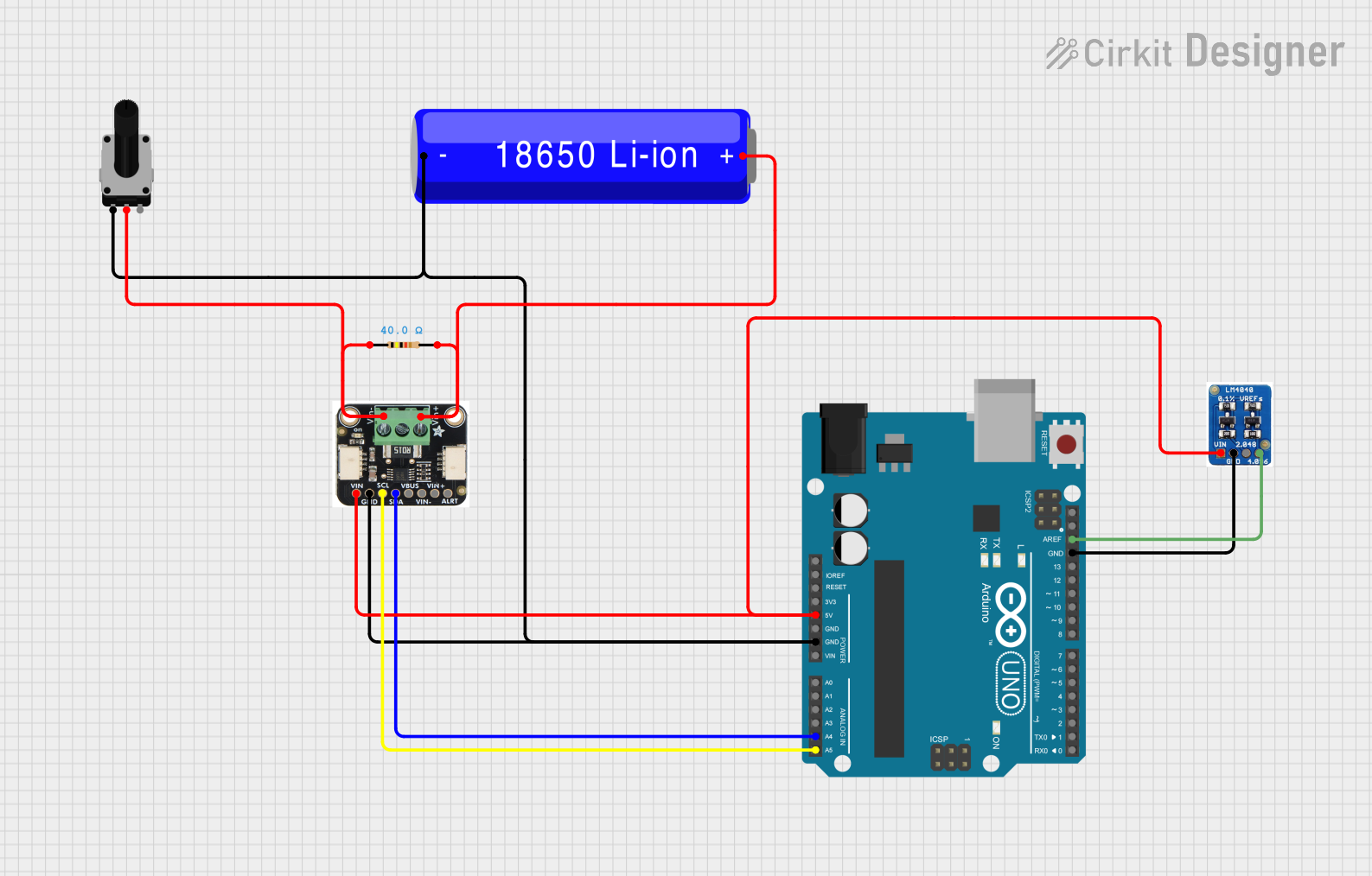

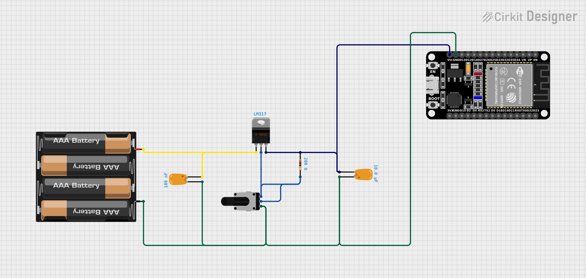
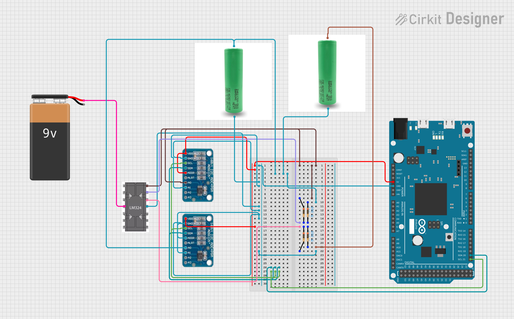
Explore Projects Built with LM4140 High Precision Low Noise Low Dropout Voltage Reference
Common Applications
- Precision analog-to-digital converters (ADCs)
- Digital-to-analog converters (DACs)
- Test and measurement equipment
- Medical instrumentation
- High-precision voltage regulation
- Calibration systems
Technical Specifications
The LM4140 is available in multiple output voltage options, such as 2.5V, 4.096V, and 5.0V. Below are the key technical details:
| Parameter | Value |
|---|---|
| Output Voltage Options | 2.5V, 4.096V, 5.0V |
| Output Voltage Accuracy | ±0.1% (typical) |
| Temperature Coefficient | 3 ppm/°C (typical) |
| Output Noise (0.1Hz to 10Hz) | 3.3 µVpp (typical) |
| Supply Voltage Range | 2.7V to 12V |
| Dropout Voltage | 100 mV (typical) |
| Output Current Capability | ±10 mA |
| Quiescent Current | 1 mA (typical) |
| Operating Temperature Range | -40°C to +125°C |
| Package Options | SOIC-8, TO-92 |
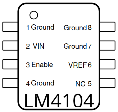
Pin Configuration and Descriptions
The LM4140 is commonly available in an 8-pin SOIC package. Below is the pinout and description:
| Pin Number | Pin Name | Description |
|---|---|---|
| 1 | NC | No connection (leave unconnected or connect to ground for stability). |
| 2 | GND | Ground pin. Connect to the circuit ground. |
| 3 | NC | No connection (leave unconnected or connect to ground for stability). |
| 4 | VIN | Input voltage. Connect to a stable power supply (2.7V to 12V). |
| 5 | VOUT | Output voltage. Provides the precise reference voltage (e.g., 2.5V, 4.096V). |
| 6 | NC | No connection (leave unconnected or connect to ground for stability). |
| 7 | NC | No connection (leave unconnected or connect to ground for stability). |
| 8 | NC | No connection (leave unconnected or connect to ground for stability). |
Usage Instructions
How to Use the LM4140 in a Circuit
- Power Supply: Connect the VIN pin to a stable power supply within the range of 2.7V to 12V. Ensure the supply voltage is at least 100 mV higher than the desired output voltage.
- Ground Connection: Connect the GND pin to the circuit ground.
- Output Voltage: The VOUT pin provides the precise reference voltage. Connect this pin to the load or the circuit requiring the reference voltage.
- Bypass Capacitors: For optimal performance, use a 0.1 µF ceramic capacitor close to the VIN pin and a 1 µF capacitor close to the VOUT pin. These capacitors help reduce noise and improve stability.
Important Considerations and Best Practices
- Thermal Management: Ensure the LM4140 operates within its specified temperature range (-40°C to +125°C). Use proper heat dissipation techniques if necessary.
- Load Regulation: Avoid connecting a load that exceeds the maximum output current of ±10 mA.
- Noise Reduction: To minimize noise, use high-quality capacitors and keep the layout traces short and direct.
- Startup Time: Allow a brief stabilization time after powering the device to ensure the output voltage reaches its specified accuracy.
Example: Using LM4140 with Arduino UNO
The LM4140 can be used as a reference voltage for ADCs in microcontrollers like the Arduino UNO. Below is an example of how to connect and use the LM4140:
Circuit Connection
- Connect the VIN pin of the LM4140 to the Arduino's 5V pin.
- Connect the GND pin of the LM4140 to the Arduino's GND pin.
- Connect the VOUT pin of the LM4140 to the AREF pin of the Arduino UNO.
- Add a 0.1 µF capacitor between VIN and GND, and a 1 µF capacitor between VOUT and GND.
Arduino Code Example
// Example: Using LM4140 as an external reference voltage for Arduino ADC

void setup() {
  // Set the analog reference to EXTERNAL to use LM4140's output
  analogReference(EXTERNAL);

  // Initialize serial communication for debugging
  Serial.begin(9600);
}

void loop() {
  // Read an analog value from pin A0
  int sensorValue = analogRead(A0);

  // Convert the analog value to voltage (assuming 2.5V reference from LM4140)
  float voltage = sensorValue * (2.5 / 1023.0);

  // Print the voltage to the Serial Monitor
  Serial.print("Voltage: ");
  Serial.print(voltage);
  Serial.println(" V");

  // Wait for 1 second before the next reading
  delay(1000);
}
Troubleshooting and FAQs
Common Issues and Solutions
Output Voltage is Incorrect
- Cause: Insufficient input voltage or excessive load current.
- Solution: Ensure the input voltage is at least 100 mV higher than the output voltage. Verify that the load current does not exceed ±10 mA.
High Noise on Output
- Cause: Missing or inadequate bypass capacitors.
- Solution: Add a 0.1 µF capacitor near the VIN pin and a 1 µF capacitor near the VOUT pin.
Device Overheating
- Cause: Excessive power dissipation or poor thermal management.
- Solution: Reduce the input voltage or improve heat dissipation (e.g., use a heatsink).
Startup Delay
- Cause: The device requires stabilization time.
- Solution: Allow a few milliseconds for the output voltage to stabilize after power-up.
FAQs
Q1: Can the LM4140 be used with a 3.3V power supply?
A1: Yes, the LM4140 can operate with a supply voltage as low as 2.7V. Ensure the input voltage is at least 100 mV higher than the desired output voltage.
Q2: What is the maximum load current the LM4140 can drive?
A2: The LM4140 can source or sink up to ±10 mA of current.
Q3: Can I use the LM4140 without bypass capacitors?
A3: While the LM4140 can function without bypass capacitors, it is highly recommended to use them to minimize noise and improve stability.
Q4: Is the LM4140 suitable for battery-powered applications?
A4: Yes, the LM4140's low quiescent current (1 mA typical) makes it suitable for battery-powered applications.