
How to Use 40A DC-DC MPPT: Examples, Pinouts, and Specs
 Design with 40A DC-DC MPPT in Cirkit Designer
Introduction
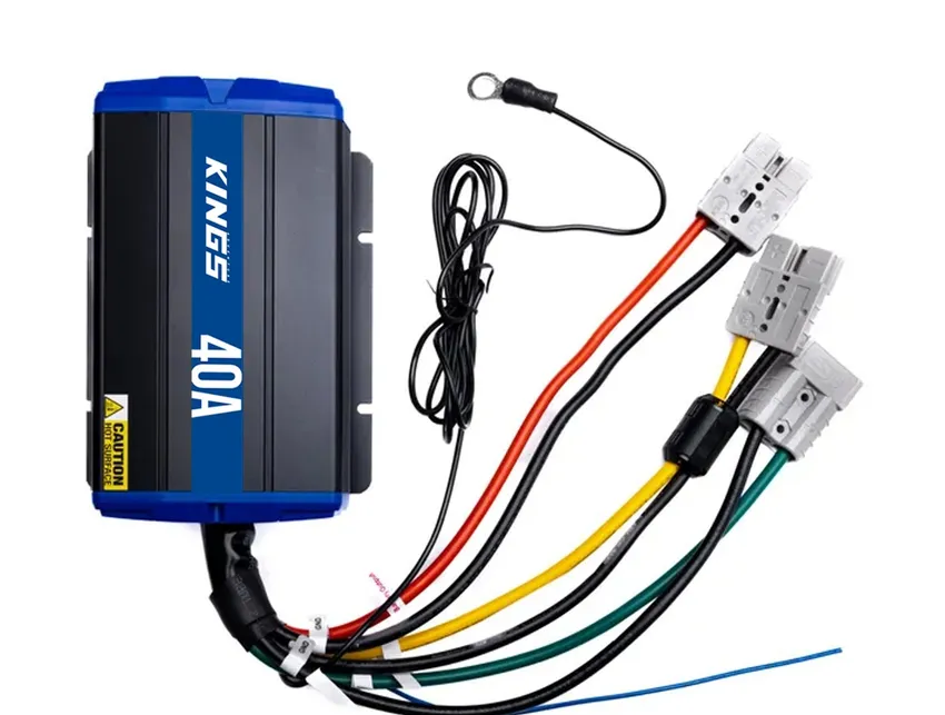
The 40A DC-DC MPPT by Kings is a high-performance Maximum Power Point Tracking (MPPT) controller designed for efficient DC-DC conversion. It is capable of handling up to 40A of current, making it ideal for renewable energy systems such as solar panels. By dynamically adjusting the electrical operating point, this MPPT controller ensures maximum power extraction from energy sources, significantly improving system efficiency.
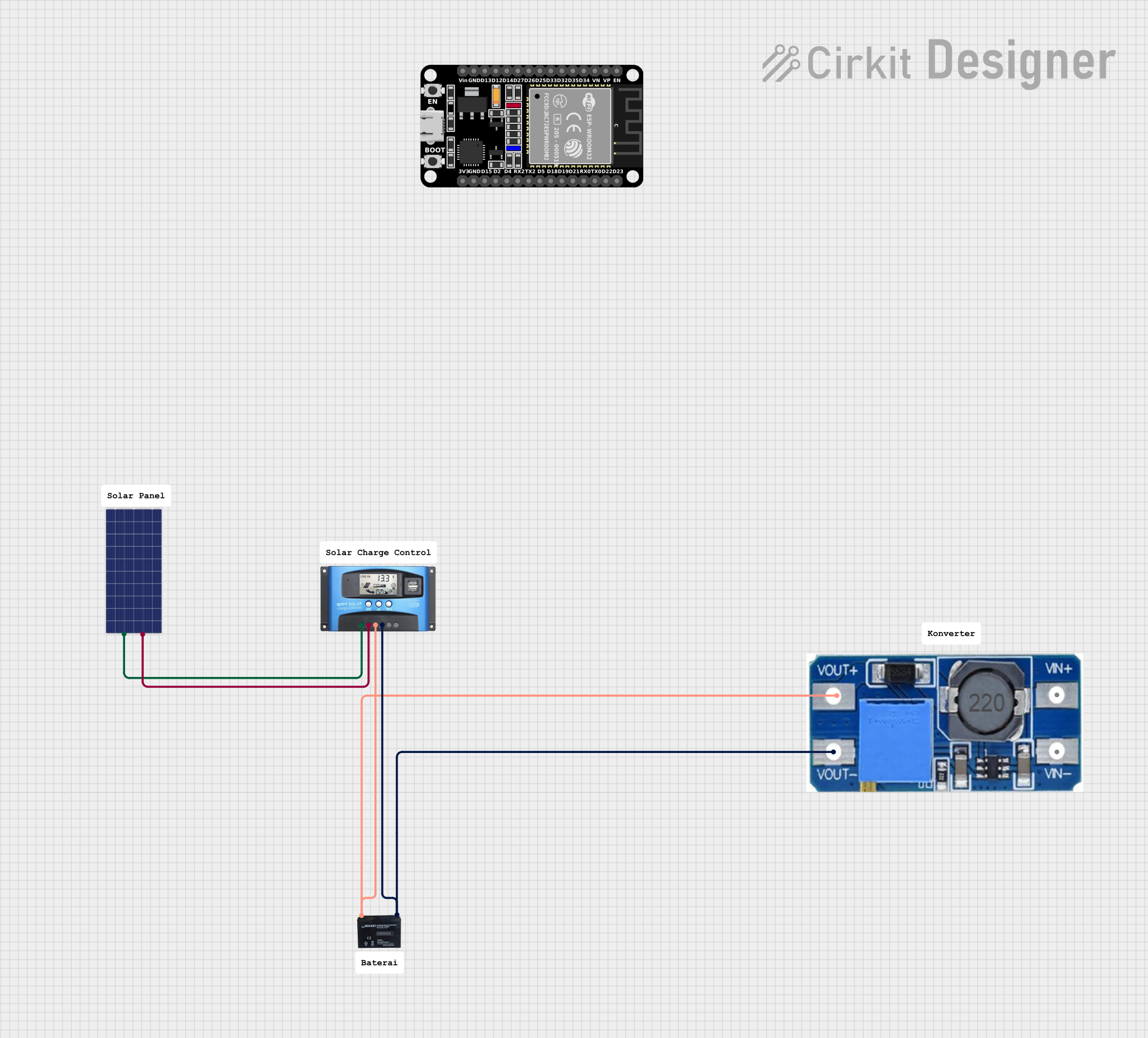
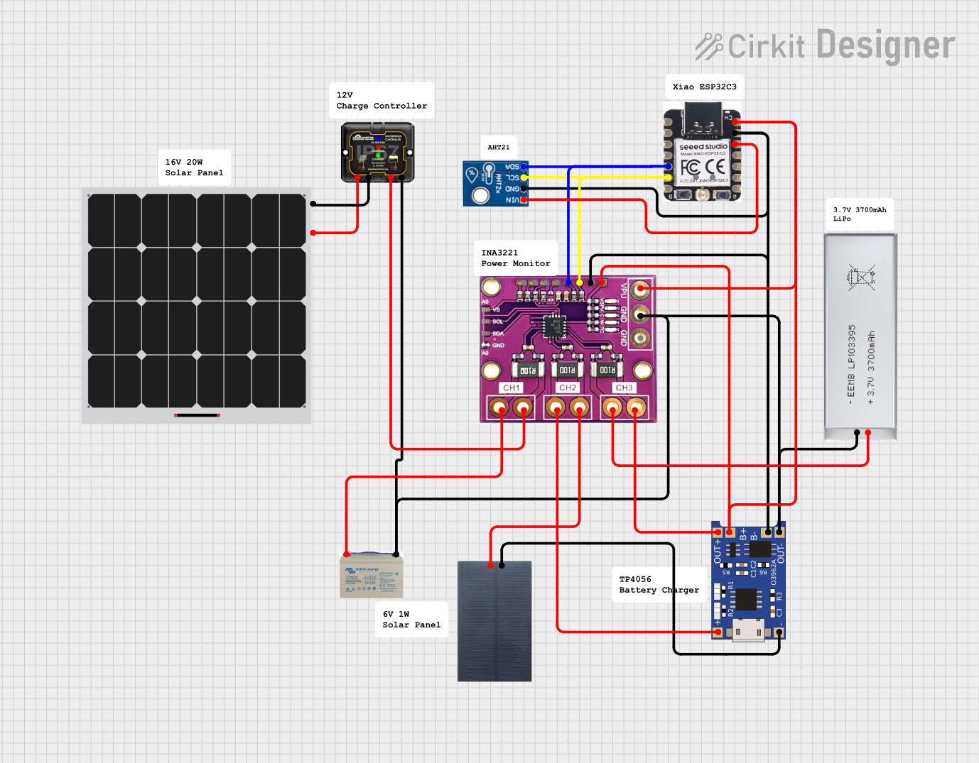
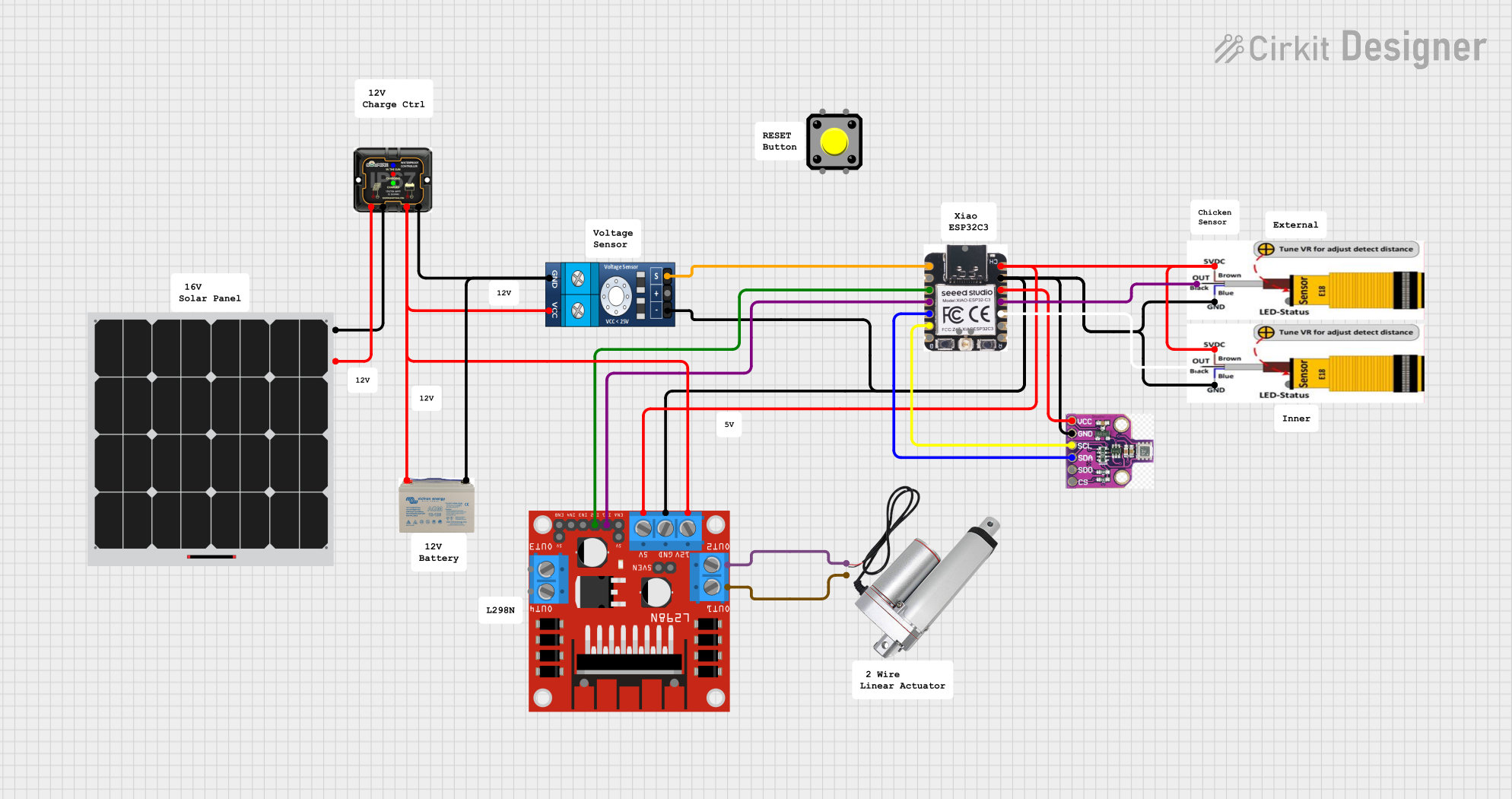
Explore Projects Built with 40A DC-DC MPPT
 Open Project in Cirkit Designer
 Open Project in Cirkit Designer
 Open Project in Cirkit Designer
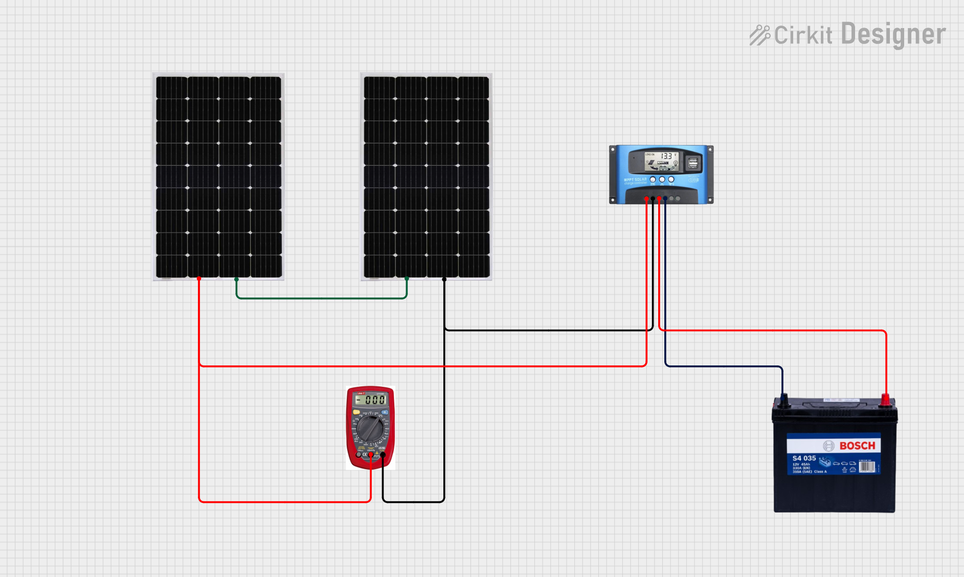 Open Project in Cirkit Designer
Explore Projects Built with 40A DC-DC MPPT
Open Project in Cirkit DesignerOpen Project in Cirkit DesignerOpen Project in Cirkit DesignerOpen Project in Cirkit DesignerCommon Applications and Use Cases
- Solar panel systems for residential, commercial, or industrial use
- Battery charging systems for off-grid or hybrid setups
- Renewable energy systems using wind or hydroelectric generators
- Electric vehicle (EV) charging stations
- DC power supply optimization in remote installations
Technical Specifications
The following table outlines the key technical details of the 40A DC-DC MPPT:
| Parameter | Value |
|---|---|
| Input Voltage Range | 12V to 60V DC |
| Output Voltage Range | 12V to 48V DC (adjustable) |
| Maximum Current | 40A |
| Efficiency | Up to 98% |
| MPPT Tracking Efficiency | ≥ 99% |
| Operating Temperature | -20°C to 60°C |
| Dimensions | 150mm x 100mm x 50mm |
| Weight | 500g |
Pin Configuration and Descriptions
The 40A DC-DC MPPT features the following input/output terminals and control pins:
| Pin/Terminal | Description |
|---|---|
| VIN+ | Positive input terminal for the DC power source (e.g., solar panel). |
| VIN- | Negative input terminal for the DC power source. |
| VOUT+ | Positive output terminal for the load or battery. |
| VOUT- | Negative output terminal for the load or battery. |
| MPPT_EN | MPPT enable pin. Connect to HIGH (5V) to enable MPPT tracking. |
| GND | Ground connection for control signals. |
| TEMP_SENSE | Input for an external temperature sensor to monitor and adjust performance. |
| STATUS_LED | Output pin for an LED to indicate operational status (e.g., MPPT active). |
Usage Instructions
How to Use the Component in a Circuit
Connect the Input Source:
- Attach the positive and negative terminals of your DC power source (e.g., solar panel) to the
VIN+andVIN-terminals, respectively. - Ensure the input voltage is within the specified range (12V to 60V DC).
- Attach the positive and negative terminals of your DC power source (e.g., solar panel) to the
Connect the Output Load or Battery:
- Connect the positive and negative terminals of your load or battery to the
VOUT+andVOUT-terminals, respectively. - Adjust the output voltage using the onboard potentiometer or control interface, if applicable.
- Connect the positive and negative terminals of your load or battery to the
Enable MPPT Tracking:
- Connect the
MPPT_ENpin to a HIGH signal (5V) to activate the MPPT functionality. - Optionally, connect an LED to the
STATUS_LEDpin to monitor the MPPT status.
- Connect the
Monitor Temperature (Optional):
- Attach an external temperature sensor to the
TEMP_SENSEpin for thermal management and performance optimization.
- Attach an external temperature sensor to the
Power On:
- Once all connections are secure, power on the system and observe the operational status via the
STATUS_LEDor other indicators.
- Once all connections are secure, power on the system and observe the operational status via the
Important Considerations and Best Practices
- Input Voltage: Ensure the input voltage is within the specified range to avoid damage to the controller.
- Heat Dissipation: The controller may generate heat during operation. Use adequate heat sinks or cooling mechanisms if operating near the maximum current (40A).
- Wiring: Use appropriately rated wires for both input and output connections to handle high currents safely.
- Polarity: Double-check the polarity of all connections to prevent damage to the component or connected devices.
- Battery Charging: When charging batteries, ensure the output voltage is set according to the battery's specifications to prevent overcharging or undercharging.
Example Code for Arduino UNO Integration
The 40A DC-DC MPPT can be controlled and monitored using an Arduino UNO. Below is an example code snippet to enable MPPT tracking and monitor the status LED:
// Pin Definitions
const int mpptEnablePin = 7;  // Pin connected to MPPT_EN
const int statusLedPin = 8;   // Pin connected to STATUS_LED

void setup() {
  // Initialize pins
  pinMode(mpptEnablePin, OUTPUT);
  pinMode(statusLedPin, INPUT);

  // Enable MPPT tracking
  digitalWrite(mpptEnablePin, HIGH);

  // Begin serial communication for monitoring
  Serial.begin(9600);
}

void loop() {
  // Read the status LED pin
  int status = digitalRead(statusLedPin);

  // Print MPPT status to the serial monitor
  if (status == HIGH) {
    Serial.println("MPPT is active and tracking.");
  } else {
    Serial.println("MPPT is inactive.");
  }

  // Add a delay for readability
  delay(1000);
}
Troubleshooting and FAQs
Common Issues and Solutions
No Output Voltage:
- Cause: Incorrect wiring or input voltage out of range.
- Solution: Verify all connections and ensure the input voltage is within the 12V to 60V range.
MPPT Not Activating:
- Cause:
MPPT_ENpin not connected or set to LOW. - Solution: Ensure the
MPPT_ENpin is connected to a HIGH signal (5V).
- Cause:
Overheating:
- Cause: Insufficient cooling or operating near maximum current.
- Solution: Add heat sinks or active cooling (e.g., fans) to dissipate heat effectively.
Fluctuating Output Voltage:
- Cause: Unstable input source or incorrect output voltage setting.
- Solution: Stabilize the input source and adjust the output voltage using the potentiometer.
FAQs
Q1: Can this MPPT controller be used with wind turbines?
A1: Yes, as long as the input voltage is within the 12V to 60V range, it can be used with wind turbines.
Q2: How do I know if MPPT is active?
A2: Connect an LED to the STATUS_LED pin. When MPPT is active, the LED will light up.
Q3: Can I use this controller for lithium-ion battery charging?
A3: Yes, but ensure the output voltage is configured to match the charging requirements of your lithium-ion battery pack.
Q4: What happens if the input voltage exceeds 60V?
A4: Exceeding the input voltage range may damage the controller. Use a voltage regulator or limiter to prevent this.
By following this documentation, users can effectively integrate and operate the 40A DC-DC MPPT in their renewable energy systems.