How to Use Stromwandler LEM CASR25: Examples, Pinouts, and Specs
Introduction
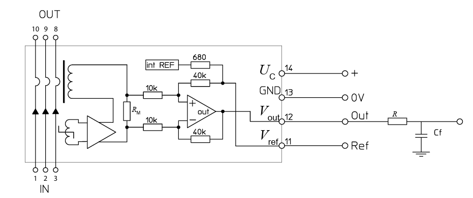
The LEM CASR25 is a high-performance current transducer designed for accurate measurement of both AC and DC currents. It employs Hall effect technology to achieve galvanic isolation between the primary circuit (high power) and the secondary circuit (measurement). This ensures safety and precision in current sensing applications. The CASR25 is widely used in industrial systems, renewable energy solutions, power monitoring, and motor control applications.
Explore Projects Built with Stromwandler LEM CASR25


Explore Projects Built with Stromwandler LEM CASR25
Common Applications
- Industrial automation and motor drives
- Renewable energy systems (e.g., solar inverters, wind turbines)
- Power monitoring and energy management systems
- Battery management systems (BMS)
- Uninterruptible power supplies (UPS)
Technical Specifications
Key Technical Details
| Parameter | Value |
|---|---|
| Nominal Primary Current | ±25 A |
| Measurement Range | ±37.5 A |
| Supply Voltage (Vcc) | 5 V DC |
| Output Voltage Range | 0.625 V to 4.375 V |
| Accuracy | ±0.5% of nominal current |
| Bandwidth | DC to 100 kHz |
| Galvanic Isolation Voltage | 4.3 kV RMS |
| Operating Temperature | -40°C to +85°C |
| Power Consumption | 15 mA (typical) |
Pin Configuration and Descriptions
The LEM CASR25 has a 5-pin configuration. The table below describes each pin:
| Pin Number | Pin Name | Description |
|---|---|---|
| 1 | Vcc | Power supply input (5 V DC) |
| 2 | GND | Ground connection |
| 3 | Vout | Analog output voltage proportional to current |
| 4 | Ref | Reference voltage (typically 2.5 V) |
| 5 | NC | Not connected (leave unconnected) |
Usage Instructions
How to Use the LEM CASR25 in a Circuit
- Power Supply: Connect the Vcc pin to a stable 5 V DC power source and the GND pin to the ground of the circuit.
- Current Measurement: Pass the current-carrying conductor through the transducer's primary aperture. Ensure the conductor is properly aligned for accurate measurement.
- Output Signal: The Vout pin provides an analog voltage proportional to the measured current. The output voltage is centered around the reference voltage (2.5 V) and varies linearly with the current.
- For positive currents, the output voltage increases above 2.5 V.
- For negative currents, the output voltage decreases below 2.5 V.
- Reference Voltage: The Ref pin outputs a stable 2.5 V reference voltage. This can be used as a reference for ADCs or other measurement systems.
Important Considerations
- Galvanic Isolation: Ensure that the primary and secondary circuits remain electrically isolated to maintain safety and accuracy.
- Filtering: For applications requiring high precision, consider adding a low-pass filter to the Vout pin to reduce noise.
- Temperature Effects: The CASR25 is temperature-compensated, but extreme temperature variations may slightly affect accuracy.
- Mounting: Secure the transducer to avoid mechanical vibrations, which could introduce noise or inaccuracies.
Example: Connecting to an Arduino UNO
The LEM CASR25 can be easily interfaced with an Arduino UNO for current measurement. Below is an example code snippet:
// LEM CASR25 Current Measurement with Arduino UNO
// Vout is connected to A0 (Analog Pin 0)
// Ref is connected to A1 (Analog Pin 1)

const int voutPin = A0;  // Analog pin for Vout
const int refPin = A1;   // Analog pin for Ref
const float refVoltage = 2.5;  // Reference voltage (in volts)
const float sensitivity = 0.04; // Sensitivity (V/A) for CASR25

void setup() {
  Serial.begin(9600);  // Initialize serial communication
  pinMode(voutPin, INPUT);
  pinMode(refPin, INPUT);
}

void loop() {
  // Read the analog values from Vout and Ref pins
  float vout = analogRead(voutPin) * (5.0 / 1023.0);  // Convert to voltage
  float vref = analogRead(refPin) * (5.0 / 1023.0);   // Convert to voltage

  // Calculate the current based on the output voltage
  float current = (vout - vref) / sensitivity;

  // Print the measured current to the Serial Monitor
  Serial.print("Measured Current: ");
  Serial.print(current, 2);  // Print current with 2 decimal places
  Serial.println(" A");

  delay(500);  // Wait for 500 ms before the next reading
}
Notes:
- Ensure the Arduino's analog reference voltage is set to 5 V for accurate readings.
- Use proper shielding and grounding to minimize noise in the measurement.
Troubleshooting and FAQs
Common Issues and Solutions
No Output Signal:
- Verify that the Vcc and GND pins are properly connected to a 5 V power source.
- Ensure the current-carrying conductor is correctly positioned through the transducer's aperture.
Inaccurate Measurements:
- Check for noise or interference in the circuit. Add a low-pass filter if necessary.
- Confirm that the reference voltage (Ref pin) is stable at 2.5 V.
- Ensure the conductor is centered in the aperture for optimal accuracy.
Output Voltage Stuck at 2.5 V:
- This indicates no current is flowing through the primary conductor. Verify the load and connections.
Temperature Drift:
- While the CASR25 is temperature-compensated, extreme temperature changes may cause slight deviations. Use additional compensation in software if needed.
FAQs
Q: Can the CASR25 measure both AC and DC currents?
A: Yes, the CASR25 is designed to measure both AC and DC currents with high accuracy.
Q: What is the maximum current the CASR25 can measure?
A: The CASR25 has a nominal range of ±25 A and can measure up to ±37.5 A with reduced accuracy.
Q: Is the CASR25 suitable for high-frequency applications?
A: Yes, the CASR25 has a bandwidth of up to 100 kHz, making it suitable for high-frequency current measurements.
Q: Can I use the CASR25 with a 3.3 V microcontroller?
A: The CASR25 requires a 5 V power supply, but its output can be interfaced with a 3.3 V microcontroller using a voltage divider or level shifter.
Q: How do I ensure safety when using the CASR25?
A: Always maintain proper isolation between the primary (high power) and secondary (measurement) circuits. Follow standard safety practices for high-voltage systems.