Cirkit Designer Logo
Cirkit Designer
Your all-in-one circuit design IDE
Home / 
Component Documentation

How to Use MIC5014: Examples, Pinouts, and Specs

Image of MIC5014
Cirkit Designer LogoDesign with MIC5014 in Cirkit Designer

Introduction

The MIC5014, manufactured by Micrel, is a high-speed, low-power, dual-channel analog switch designed for signal routing and multiplexing applications. It features low on-resistance and fast switching times, making it ideal for handling high-frequency signals with minimal distortion. The MIC5014 is commonly used in audio, video, and data communication systems, as well as in test and measurement equipment.

Explore Projects Built with MIC5014

Use Cirkit Designer to design, explore, and prototype these projects online. Some projects support real-time simulation. Click "Open Project" to start designing instantly!
Arduino Mega 2560 Based Security System with Fingerprint Authentication and SMS Alerts
Image of Door security system: A project utilizing MIC5014 in a practical application
This circuit features an Arduino Mega 2560 microcontroller interfaced with a SIM800L GSM module, two fingerprint scanners, an I2C LCD display, an IR sensor, and a piezo buzzer. Power management is handled by a PowerBoost 1000 Basic Pad USB, a TP4056 charging module, and a Li-ion 18650 battery, with an option to use a Mini AC-DC 110V-230V to 5V 700mA module for direct power supply. The primary functionality appears to be a security system with GSM communication capabilities, biometric access control, and visual/audible feedback.
Cirkit Designer LogoOpen Project in Cirkit Designer
Arduino UNO RFID Access Control System with LCD Feedback and Servo Operation
Image of door lock: A project utilizing MIC5014 in a practical application
This circuit features an Arduino UNO as the central microcontroller, interfaced with an RFID-RC522 module for RFID reading capabilities, and a 16x2 LCD screen with I2C for display. It also includes a 4x4 membrane matrix keypad for user input, a buzzer for audio feedback, and two Tower Pro SG90 servos for actuation. The MB102 Breadboard Power Supply Module provides power to the servos, while the Arduino powers the other components.
Cirkit Designer LogoOpen Project in Cirkit Designer
Arduino 101 Based RFID and GSM Security System with I2C LCD Display and RTC
Image of id scanner with messaging system: A project utilizing MIC5014 in a practical application
This circuit features an Arduino 101 microcontroller interfaced with an RFID-RC522 module for RFID reading, a GSM SIM900 module for cellular communication, a DS3231 Real Time Clock for timekeeping, and an I2C LCD screen for display. The Arduino controls a buzzer connected to its D7 pin and communicates with the GSM module via serial connection on pins D0/RX and D1/TX. The RFID, RTC, and LCD modules are powered by the Arduino's 5V and 3.3V outputs, and they use I2C (SCL/SDA) for communication, except for the RFID module which uses SPI (MISO/MOSI/SCK) and a digital pin for reset (D9).
Cirkit Designer LogoOpen Project in Cirkit Designer
NFC-Enabled Access Control System with Time Logging
Image of doorlock: A project utilizing MIC5014 in a practical application
This circuit is designed for access control with time tracking capabilities. It features an NFC/RFID reader for authentication, an RTC module (DS3231) for real-time clock functionality, and an OLED display for user interaction. A 12V relay controls a magnetic lock, which is activated upon successful NFC/RFID authentication, and a button switch is likely used for manual operation or input. The T8_S3 microcontroller serves as the central processing unit, interfacing with the NFC/RFID reader, RTC, OLED, and relay to manage the access control logic.
Cirkit Designer LogoOpen Project in Cirkit Designer

Explore Projects Built with MIC5014

Use Cirkit Designer to design, explore, and prototype these projects online. Some projects support real-time simulation. Click "Open Project" to start designing instantly!
Image of Door security system: A project utilizing MIC5014 in a practical application
Arduino Mega 2560 Based Security System with Fingerprint Authentication and SMS Alerts
This circuit features an Arduino Mega 2560 microcontroller interfaced with a SIM800L GSM module, two fingerprint scanners, an I2C LCD display, an IR sensor, and a piezo buzzer. Power management is handled by a PowerBoost 1000 Basic Pad USB, a TP4056 charging module, and a Li-ion 18650 battery, with an option to use a Mini AC-DC 110V-230V to 5V 700mA module for direct power supply. The primary functionality appears to be a security system with GSM communication capabilities, biometric access control, and visual/audible feedback.
Cirkit Designer LogoOpen Project in Cirkit Designer
Image of door lock: A project utilizing MIC5014 in a practical application
Arduino UNO RFID Access Control System with LCD Feedback and Servo Operation
This circuit features an Arduino UNO as the central microcontroller, interfaced with an RFID-RC522 module for RFID reading capabilities, and a 16x2 LCD screen with I2C for display. It also includes a 4x4 membrane matrix keypad for user input, a buzzer for audio feedback, and two Tower Pro SG90 servos for actuation. The MB102 Breadboard Power Supply Module provides power to the servos, while the Arduino powers the other components.
Cirkit Designer LogoOpen Project in Cirkit Designer
Image of id scanner with messaging system: A project utilizing MIC5014 in a practical application
Arduino 101 Based RFID and GSM Security System with I2C LCD Display and RTC
This circuit features an Arduino 101 microcontroller interfaced with an RFID-RC522 module for RFID reading, a GSM SIM900 module for cellular communication, a DS3231 Real Time Clock for timekeeping, and an I2C LCD screen for display. The Arduino controls a buzzer connected to its D7 pin and communicates with the GSM module via serial connection on pins D0/RX and D1/TX. The RFID, RTC, and LCD modules are powered by the Arduino's 5V and 3.3V outputs, and they use I2C (SCL/SDA) for communication, except for the RFID module which uses SPI (MISO/MOSI/SCK) and a digital pin for reset (D9).
Cirkit Designer LogoOpen Project in Cirkit Designer
Image of doorlock: A project utilizing MIC5014 in a practical application
NFC-Enabled Access Control System with Time Logging
This circuit is designed for access control with time tracking capabilities. It features an NFC/RFID reader for authentication, an RTC module (DS3231) for real-time clock functionality, and an OLED display for user interaction. A 12V relay controls a magnetic lock, which is activated upon successful NFC/RFID authentication, and a button switch is likely used for manual operation or input. The T8_S3 microcontroller serves as the central processing unit, interfacing with the NFC/RFID reader, RTC, OLED, and relay to manage the access control logic.
Cirkit Designer LogoOpen Project in Cirkit Designer

Common Applications:

  • Signal routing in audio and video systems
  • Multiplexing in data communication circuits
  • Test and measurement equipment
  • Analog signal switching in embedded systems

Technical Specifications

Key Technical Details:

  • Supply Voltage (VDD): 2.7V to 5.5V
  • On-Resistance (RON): Typically 2.5Ω at 5V
  • Switching Time:
    • Turn-On Time: 20ns (typical)
    • Turn-Off Time: 15ns (typical)
  • Analog Signal Range: 0V to VDD
  • Power Consumption: Low-power operation
  • Channel Configuration: Dual-channel (2 independent switches)
  • Operating Temperature Range: -40°C to +85°C
  • Package Options: SOIC-8, MSOP-8

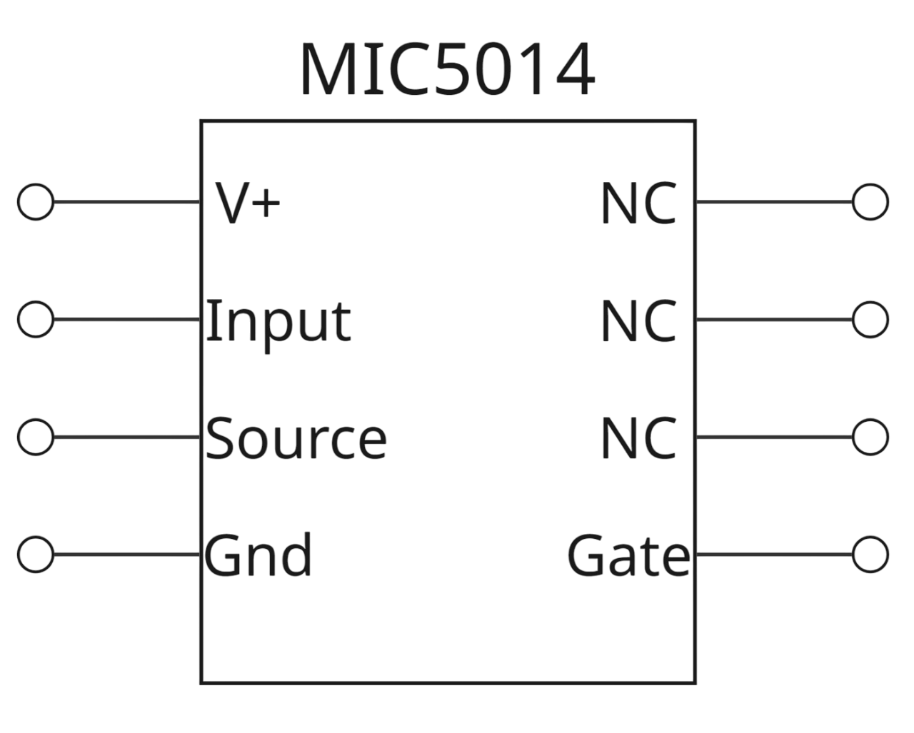
Pin Configuration and Descriptions:

The MIC5014 is available in an 8-pin package. The pinout and descriptions are as follows:

Pin Number Pin Name Description
1 IN1 Control input for Switch 1
2 GND Ground (0V reference)
3 IN2 Control input for Switch 2
4 VDD Positive supply voltage (2.7V to 5.5V)
5 OUT2 Output of Switch 2
6 COM2 Common terminal for Switch 2
7 COM1 Common terminal for Switch 1
8 OUT1 Output of Switch 1

Usage Instructions

How to Use the MIC5014 in a Circuit:

  1. Power Supply:

    • Connect the VDD pin to a stable power supply within the range of 2.7V to 5.5V.
    • Connect the GND pin to the ground of the circuit.
  2. Control Inputs:

    • Apply a logic signal (0V or VDD) to the IN1 and IN2 pins to control the state of the switches.
    • A logic HIGH (VDD) on IN1 or IN2 will close the corresponding switch, connecting COM1 to OUT1 or COM2 to OUT2, respectively.
    • A logic LOW (0V) will open the switch, disconnecting the terminals.
  3. Signal Connections:

    • Connect the analog signal source to the COM1 or COM2 pins.
    • The switched signal will appear at OUT1 or OUT2 when the corresponding switch is closed.
  4. Bypass Capacitors:

    • Place a 0.1µF ceramic capacitor close to the VDD pin to ensure stable operation and reduce noise.

Important Considerations and Best Practices:

  • Ensure that the analog signal voltage does not exceed the supply voltage (VDD).
  • Minimize trace lengths for high-frequency signals to reduce parasitic capacitance and signal degradation.
  • Use proper decoupling capacitors to maintain stable operation in noisy environments.
  • Avoid exceeding the maximum ratings specified in the datasheet to prevent damage to the component.

Example: Using MIC5014 with Arduino UNO

The MIC5014 can be controlled using digital output pins of an Arduino UNO. Below is an example code to toggle the switches:

// Define control pins for MIC5014
const int controlPin1 = 2; // Connect to IN1 of MIC5014
const int controlPin2 = 3; // Connect to IN2 of MIC5014

void setup() {
  // Set control pins as outputs
  pinMode(controlPin1, OUTPUT);
  pinMode(controlPin2, OUTPUT);
}

void loop() {
  // Close Switch 1 and open Switch 2
  digitalWrite(controlPin1, HIGH); // Logic HIGH to IN1
  digitalWrite(controlPin2, LOW);  // Logic LOW to IN2
  delay(1000); // Wait for 1 second

  // Open Switch 1 and close Switch 2
  digitalWrite(controlPin1, LOW);  // Logic LOW to IN1
  digitalWrite(controlPin2, HIGH); // Logic HIGH to IN2
  delay(1000); // Wait for 1 second
}

Troubleshooting and FAQs

Common Issues and Solutions:

  1. Switch Not Responding to Control Signal:

    • Verify that the control signal voltage levels match the VDD supply voltage.
    • Check for loose or incorrect connections to the IN1 and IN2 pins.
  2. Signal Distortion or Attenuation:

    • Ensure that the analog signal voltage is within the specified range (0V to VDD).
    • Minimize the length of signal traces to reduce parasitic effects.
  3. Excessive Power Consumption:

    • Check for proper decoupling capacitors near the VDD pin.
    • Ensure that the control signals are not left floating; they should always be driven HIGH or LOW.
  4. Component Overheating:

    • Verify that the supply voltage does not exceed the maximum rating of 5.5V.
    • Ensure that the load connected to the switches does not draw excessive current.

FAQs:

Q1: Can the MIC5014 handle AC signals?
A1: Yes, the MIC5014 can handle AC signals as long as the signal voltage stays within the range of 0V to VDD.

Q2: What is the maximum frequency the MIC5014 can switch?
A2: The MIC5014 is capable of switching signals with frequencies up to several MHz, depending on the load and circuit design.

Q3: Can I use the MIC5014 with a 3.3V microcontroller?
A3: Yes, the MIC5014 operates with supply voltages as low as 2.7V, making it compatible with 3.3V systems.

Q4: Is the MIC5014 suitable for audio applications?
A4: Yes, the low on-resistance and fast switching times make the MIC5014 suitable for audio signal routing and switching.

By following the guidelines and best practices outlined in this documentation, you can effectively integrate the MIC5014 into your electronic designs.