Cirkit Designer Logo
Cirkit Designer
Your all-in-one circuit design IDE
Home / 
Component Documentation

How to Use Adafruit FONA 808 Shield: Examples, Pinouts, and Specs

Image of Adafruit FONA 808 Shield
Cirkit Designer LogoDesign with Adafruit FONA 808 Shield in Cirkit Designer

Introduction

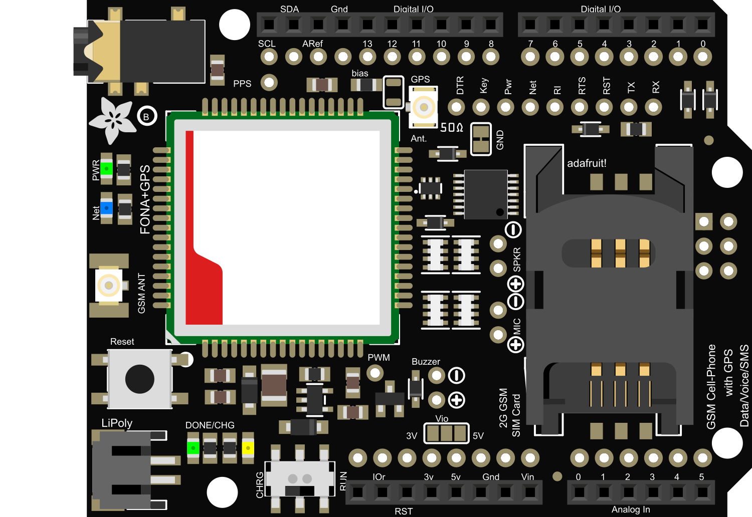
The Adafruit FONA 808 Shield is an all-in-one cellular phone module with integrated GPS, providing global data connectivity and location tracking capabilities for your Arduino projects. It combines a GSM/GPRS module with a satellite-based GPS receiver, making it ideal for a wide range of applications such as remote monitoring, asset tracking, and IoT devices. The shield is designed to work with 2G networks and supports voice calls, SMS messages, and GPRS data.

Explore Projects Built with Adafruit FONA 808 Shield

Use Cirkit Designer to design, explore, and prototype these projects online. Some projects support real-time simulation. Click "Open Project" to start designing instantly!
Raspberry Pi 4B-Based GPS and GSM Tracking System with Audio Feedback
Image of unlimited range: A project utilizing Adafruit FONA 808 Shield in a practical application
This circuit features a Raspberry Pi 4B as the central processing unit, interfaced with a GPS NEO-6M V2 module for location tracking and an Adafruit FONA 808 Shield for cellular communication. It includes a PAM8406 5V Digital Audio Amplifier connected to an Adafruit STEMMA Speaker for audio output, and a Condenser Microphone connected to the FONA 808 for audio input. Power management is handled by a 12V battery connected to a voltage regulator that steps down the voltage to 5V and 3V required by the various components.
Cirkit Designer LogoOpen Project in Cirkit Designer
Arduino-Based Temperature Monitoring System with RGB LED Feedback and I2C LCD Display
Image of wemos custom shield: A project utilizing Adafruit FONA 808 Shield in a practical application
This circuit features an Adafruit Proto Shield R3 configured with a DS18B20 temperature sensor, a WS2812 RGB LED matrix, and an LCD I2C display. The microcontroller on the Proto Shield reads the temperature from the DS18B20 sensor and displays it on the LCD. It also controls the LED matrix to show random colors and indicates temperature status with onboard LEDs.
Cirkit Designer LogoOpen Project in Cirkit Designer
Raspberry Pi 4B-Based Multi-Sensor Interface Hub with GPS and GSM
Image of Rocket: A project utilizing Adafruit FONA 808 Shield in a practical application
This circuit features a Raspberry Pi 4B interfaced with an IMX296 color global shutter camera, a Neo 6M GPS module, an Adafruit BMP388 barometric pressure sensor, an MPU-6050 accelerometer/gyroscope, and a Sim800l GSM module for cellular connectivity. Power management is handled by an MT3608 boost converter, which steps up the voltage from a Lipo battery, with a resettable fuse PTC and a 1N4007 diode for protection. The Adafruit Perma-Proto HAT is used for organizing connections and interfacing the sensors and modules with the Raspberry Pi via I2C and GPIO pins.
Cirkit Designer LogoOpen Project in Cirkit Designer
Arduino Sensor Shield with I2C LCD and Bluetooth Interface
Image of wallE: A project utilizing Adafruit FONA 808 Shield in a practical application
This circuit features an Arduino Sensor Shield v5.0 interfaced with an I2C LCD Display and an HC-05 Bluetooth Module. The LCD Display is connected for power, ground, and I2C communication, allowing it to display data or messages. The HC-05 Bluetooth Module is wired for serial communication with the Arduino Sensor Shield, enabling wireless data exchange with other Bluetooth-enabled devices.
Cirkit Designer LogoOpen Project in Cirkit Designer

Explore Projects Built with Adafruit FONA 808 Shield

Use Cirkit Designer to design, explore, and prototype these projects online. Some projects support real-time simulation. Click "Open Project" to start designing instantly!
Image of unlimited range: A project utilizing Adafruit FONA 808 Shield in a practical application
Raspberry Pi 4B-Based GPS and GSM Tracking System with Audio Feedback
This circuit features a Raspberry Pi 4B as the central processing unit, interfaced with a GPS NEO-6M V2 module for location tracking and an Adafruit FONA 808 Shield for cellular communication. It includes a PAM8406 5V Digital Audio Amplifier connected to an Adafruit STEMMA Speaker for audio output, and a Condenser Microphone connected to the FONA 808 for audio input. Power management is handled by a 12V battery connected to a voltage regulator that steps down the voltage to 5V and 3V required by the various components.
Cirkit Designer LogoOpen Project in Cirkit Designer
Image of wemos custom shield: A project utilizing Adafruit FONA 808 Shield in a practical application
Arduino-Based Temperature Monitoring System with RGB LED Feedback and I2C LCD Display
This circuit features an Adafruit Proto Shield R3 configured with a DS18B20 temperature sensor, a WS2812 RGB LED matrix, and an LCD I2C display. The microcontroller on the Proto Shield reads the temperature from the DS18B20 sensor and displays it on the LCD. It also controls the LED matrix to show random colors and indicates temperature status with onboard LEDs.
Cirkit Designer LogoOpen Project in Cirkit Designer
Image of Rocket: A project utilizing Adafruit FONA 808 Shield in a practical application
Raspberry Pi 4B-Based Multi-Sensor Interface Hub with GPS and GSM
This circuit features a Raspberry Pi 4B interfaced with an IMX296 color global shutter camera, a Neo 6M GPS module, an Adafruit BMP388 barometric pressure sensor, an MPU-6050 accelerometer/gyroscope, and a Sim800l GSM module for cellular connectivity. Power management is handled by an MT3608 boost converter, which steps up the voltage from a Lipo battery, with a resettable fuse PTC and a 1N4007 diode for protection. The Adafruit Perma-Proto HAT is used for organizing connections and interfacing the sensors and modules with the Raspberry Pi via I2C and GPIO pins.
Cirkit Designer LogoOpen Project in Cirkit Designer
Image of wallE: A project utilizing Adafruit FONA 808 Shield in a practical application
Arduino Sensor Shield with I2C LCD and Bluetooth Interface
This circuit features an Arduino Sensor Shield v5.0 interfaced with an I2C LCD Display and an HC-05 Bluetooth Module. The LCD Display is connected for power, ground, and I2C communication, allowing it to display data or messages. The HC-05 Bluetooth Module is wired for serial communication with the Arduino Sensor Shield, enabling wireless data exchange with other Bluetooth-enabled devices.
Cirkit Designer LogoOpen Project in Cirkit Designer

Common Applications and Use Cases

  • GPS tracking devices
  • Remote data logging
  • Asset tracking systems
  • Emergency systems
  • IoT devices with location services

Technical Specifications

Key Technical Details

  • Networks: 2G (GSM/GPRS)
  • Frequency Bands: 850/900/1800/1900 MHz
  • Supply Voltage: 3.4V to 4.4V
  • Operating Temperature: -40°C to +85°C
  • Data Support: GPRS multi-slot class 12/10, GPRS mobile station class B
  • GPS: Integrated GPS with 22 tracking / 66 acquisition channels
  • GPS Sensitivity: Tracking: -165 dBm

Pin Configuration and Descriptions

Pin Number Name Description
1 Vio Power supply for logic level (3.3V to 5V)
2 GND Ground
3 RST Reset pin
4 RX UART receive pin
5 TX UART transmit pin
6 Key Turn on/off the module
7 PS Power status pin
8 NS Network status pin
... ... ...

Note: This table is not exhaustive. Refer to the Adafruit FONA 808 Shield datasheet for the complete pinout and description.

Usage Instructions

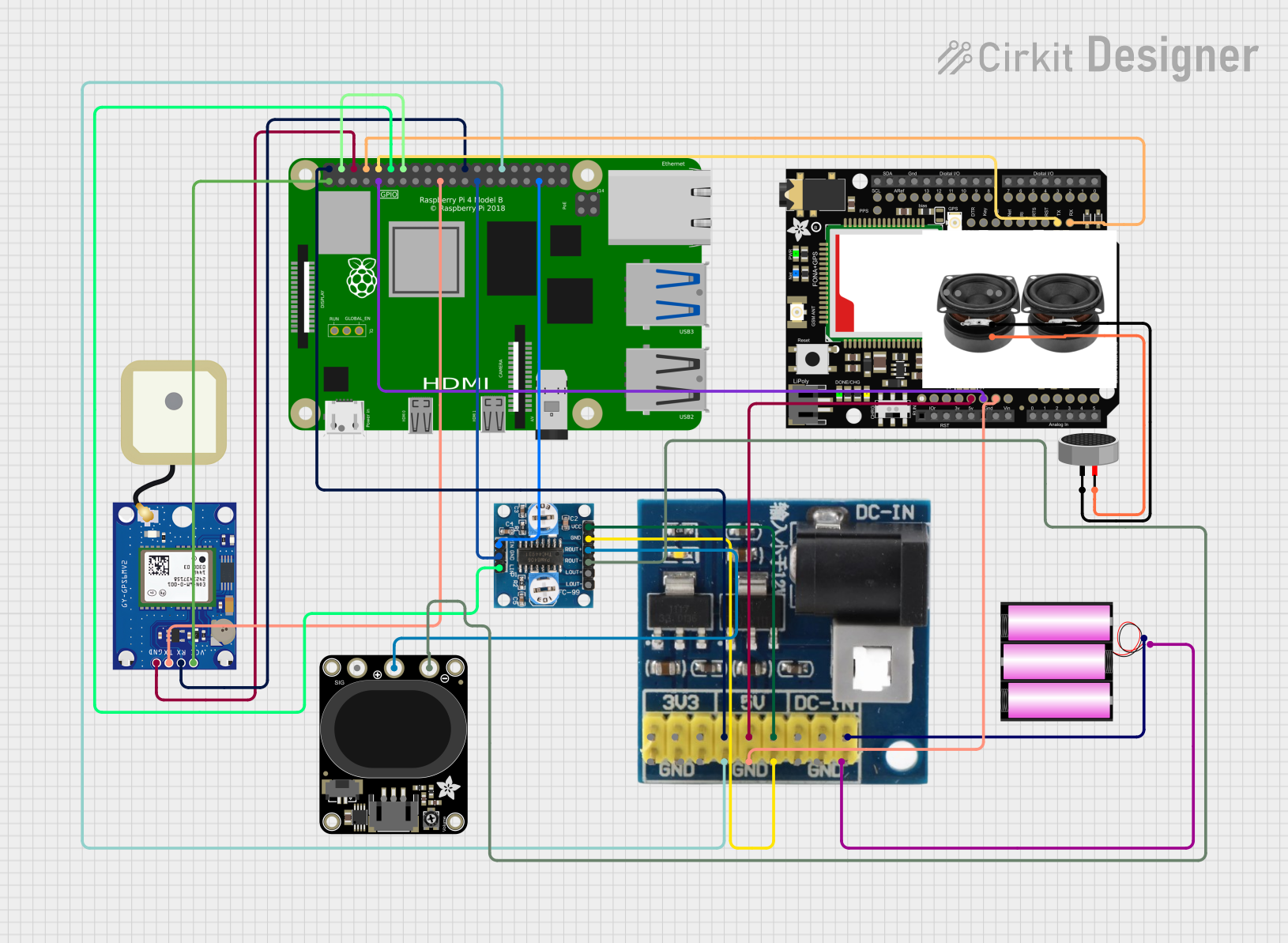
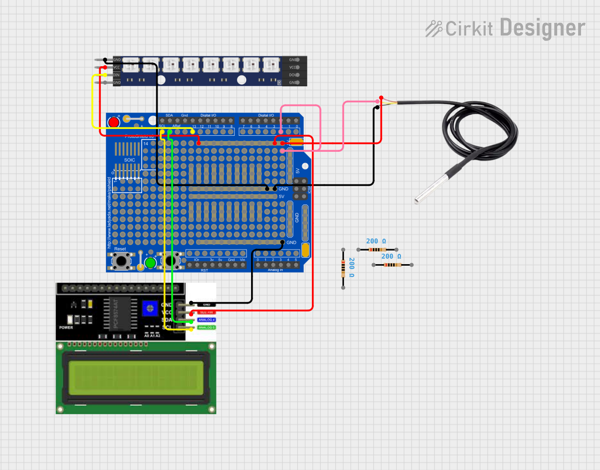
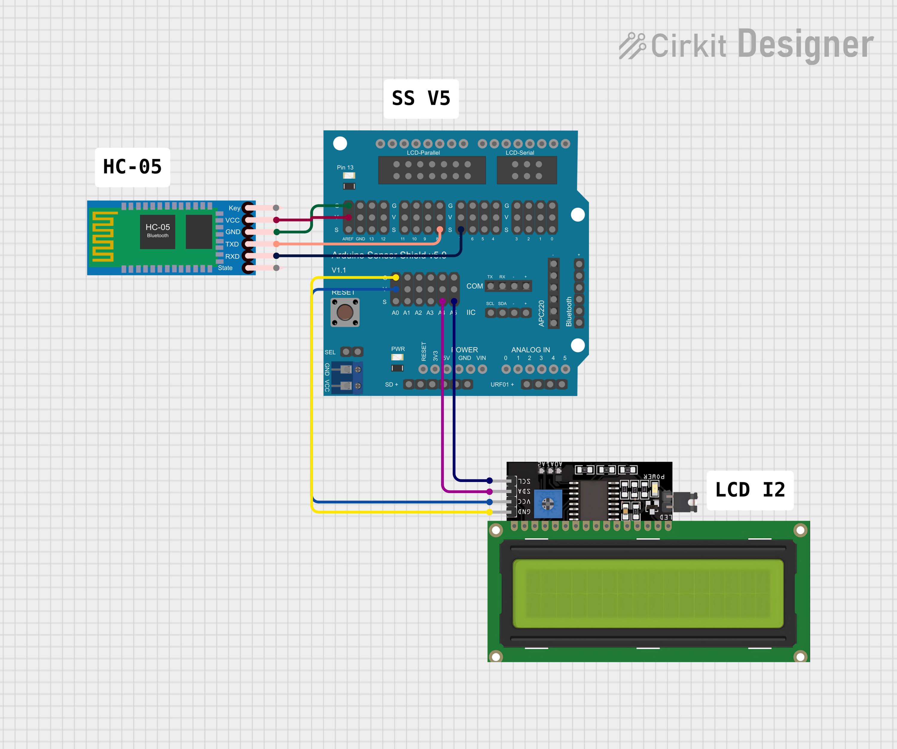
How to Use the Component in a Circuit

  1. Powering the Shield: Connect a 3.7V LiPo battery to the JST connector on the shield to power the GSM and GPS modules.
  2. Logic Level: Ensure that the Vio pin is connected to the appropriate logic level for your Arduino (3.3V or 5V).
  3. Antennas: Attach the GSM and GPS antennas to their respective U.FL connectors on the shield.
  4. SIM Card: Insert a micro SIM card into the SIM card holder.
  5. Arduino Connection: Mount the shield on top of an Arduino board, ensuring that all pins are aligned correctly.

Important Considerations and Best Practices

  • Power Requirements: The shield requires a significant amount of power during transmission. Ensure that your power source can deliver the necessary current.
  • Antenna Placement: For optimal GPS reception, place the GPS antenna with a clear view of the sky.
  • Network Compatibility: Verify that your SIM card and network provider support 2G connectivity.
  • Serial Communication: The default baud rate for the UART interface is 115200 bps. Ensure that your Arduino's serial port is configured to match this rate.

Example Arduino Code

#include <Adafruit_FONA.h>

// Pin definitions
#define FONA_RX 2
#define FONA_TX 3
#define FONA_RST 4

// Create the FONA object
Adafruit_FONA fona = Adafruit_FONA(FONA_RST);

void setup() {
  Serial.begin(115200);
  Serial.println(F("FONA basic test"));
  Serial.println(F("Initializing FONA... (may take a few seconds)"));

  // Make it slow so its easy to read!
  fonaSerial->begin(4800);
  if (! fona.begin(*fonaSerial)) {
    Serial.println(F("Couldn't find FONA"));
    while (1);
  }
  Serial.println(F("FONA is OK"));
}

void loop() {
  // Your code to interact with the FONA shield goes here
}

Note: This is a basic initialization example. For full functionality, refer to the Adafruit FONA library and examples.

Troubleshooting and FAQs

Common Issues

  • No Network Connection: Ensure the SIM card is activated and has a data plan. Check the antenna connections and placement.
  • GPS Not Fixing: Verify that the GPS antenna has a clear view of the sky. It may take several minutes to get a fix, especially on the first use.
  • Power Issues: If the shield resets during operation, it may be due to insufficient power supply. Use a battery capable of supplying at least 2A of current.

Solutions and Tips for Troubleshooting

  • Check LED Indicators: The power status and network status LEDs can provide valuable information about the shield's state.
  • Serial Communication: Use serial debugging to check for error messages or status updates from the shield.
  • Firmware Updates: Ensure that the shield's firmware is up to date with the latest version from Adafruit.

FAQs

Q: Can the FONA 808 Shield work with 3G or 4G networks? A: No, the FONA 808 is designed for 2G networks only.

Q: How do I update the firmware on the FONA 808 Shield? A: Firmware updates can be performed using the FONA flash tool provided by Adafruit. Follow the instructions on the Adafruit website for the update process.

Q: What is the power consumption of the FONA 808 Shield? A: The shield typically consumes around 250 mA during transmission and less during idle. However, it can peak up to 2A during transmission bursts.

Note: This documentation is for informational purposes only. For detailed technical specifications and advanced usage, refer to the official Adafruit FONA 808 Shield datasheet and user manual.