Cirkit Designer Logo
Cirkit Designer
Your all-in-one circuit design IDE
Home / 
Component Documentation

How to Use M5Stamp-s3: Examples, Pinouts, and Specs

Image of M5Stamp-s3
Cirkit Designer LogoDesign with M5Stamp-s3 in Cirkit Designer

Introduction

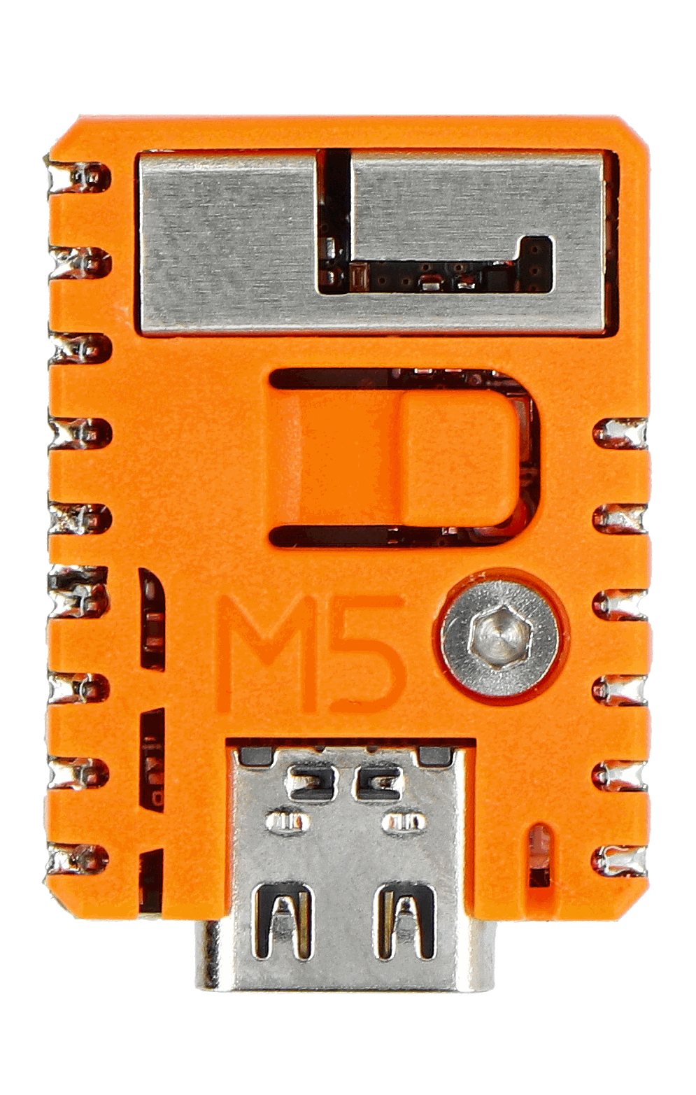
The M5Stamp-s3 is a compact, low-power microcontroller module developed by M5. It is based on the ESP32-S3 chip, which features dual-core Xtensa LX7 processors, integrated Wi-Fi, and Bluetooth 5.0 connectivity. This module is designed for Internet of Things (IoT) applications, offering a versatile platform for prototyping and deploying smart devices. Its small form factor and GPIO pins make it ideal for interfacing with a wide range of sensors, actuators, and other peripherals.

Explore Projects Built with M5Stamp-s3

Use Cirkit Designer to design, explore, and prototype these projects online. Some projects support real-time simulation. Click "Open Project" to start designing instantly!
Arduino Mega 2560 Based Security System with Fingerprint Authentication and SMS Alerts
Image of Door security system: A project utilizing M5Stamp-s3 in a practical application
This circuit features an Arduino Mega 2560 microcontroller interfaced with a SIM800L GSM module, two fingerprint scanners, an I2C LCD display, an IR sensor, and a piezo buzzer. Power management is handled by a PowerBoost 1000 Basic Pad USB, a TP4056 charging module, and a Li-ion 18650 battery, with an option to use a Mini AC-DC 110V-230V to 5V 700mA module for direct power supply. The primary functionality appears to be a security system with GSM communication capabilities, biometric access control, and visual/audible feedback.
Cirkit Designer LogoOpen Project in Cirkit Designer
NFC-Enabled Access Control System with Real-Time Clock and OLED Display
Image of doorlock: A project utilizing M5Stamp-s3 in a practical application
This circuit is designed as an access control system with time-tracking capabilities. It uses an NFC/RFID reader for authentication, a real-time clock for time-stamping events, and an OLED display for user interface, all controlled by a T8_S3 microcontroller. A relay module actuates a magnetic lock, and a button switch provides additional user input, with a switching power supply delivering the necessary voltages.
Cirkit Designer LogoOpen Project in Cirkit Designer
NFC-Enabled Access Control System with Time Logging
Image of doorlock: A project utilizing M5Stamp-s3 in a practical application
This circuit is designed for access control with time tracking capabilities. It features an NFC/RFID reader for authentication, an RTC module (DS3231) for real-time clock functionality, and an OLED display for user interaction. A 12V relay controls a magnetic lock, which is activated upon successful NFC/RFID authentication, and a button switch is likely used for manual operation or input. The T8_S3 microcontroller serves as the central processing unit, interfacing with the NFC/RFID reader, RTC, OLED, and relay to manage the access control logic.
Cirkit Designer LogoOpen Project in Cirkit Designer
Battery-Powered ESP32-S3 Controlled Servo System with gForceJoint UART
Image of Copy of Oymotion: A project utilizing M5Stamp-s3 in a practical application
This circuit is a servo control system powered by a 4 x AAA battery pack, regulated by a step-down DC regulator. An ESP32-S3 microcontroller controls five servos and communicates with a gForceJoint UART sensor, enabling precise servo movements based on sensor inputs.
Cirkit Designer LogoOpen Project in Cirkit Designer

Explore Projects Built with M5Stamp-s3

Use Cirkit Designer to design, explore, and prototype these projects online. Some projects support real-time simulation. Click "Open Project" to start designing instantly!
Image of Door security system: A project utilizing M5Stamp-s3 in a practical application
Arduino Mega 2560 Based Security System with Fingerprint Authentication and SMS Alerts
This circuit features an Arduino Mega 2560 microcontroller interfaced with a SIM800L GSM module, two fingerprint scanners, an I2C LCD display, an IR sensor, and a piezo buzzer. Power management is handled by a PowerBoost 1000 Basic Pad USB, a TP4056 charging module, and a Li-ion 18650 battery, with an option to use a Mini AC-DC 110V-230V to 5V 700mA module for direct power supply. The primary functionality appears to be a security system with GSM communication capabilities, biometric access control, and visual/audible feedback.
Cirkit Designer LogoOpen Project in Cirkit Designer
Image of doorlock: A project utilizing M5Stamp-s3 in a practical application
NFC-Enabled Access Control System with Real-Time Clock and OLED Display
This circuit is designed as an access control system with time-tracking capabilities. It uses an NFC/RFID reader for authentication, a real-time clock for time-stamping events, and an OLED display for user interface, all controlled by a T8_S3 microcontroller. A relay module actuates a magnetic lock, and a button switch provides additional user input, with a switching power supply delivering the necessary voltages.
Cirkit Designer LogoOpen Project in Cirkit Designer
Image of doorlock: A project utilizing M5Stamp-s3 in a practical application
NFC-Enabled Access Control System with Time Logging
This circuit is designed for access control with time tracking capabilities. It features an NFC/RFID reader for authentication, an RTC module (DS3231) for real-time clock functionality, and an OLED display for user interaction. A 12V relay controls a magnetic lock, which is activated upon successful NFC/RFID authentication, and a button switch is likely used for manual operation or input. The T8_S3 microcontroller serves as the central processing unit, interfacing with the NFC/RFID reader, RTC, OLED, and relay to manage the access control logic.
Cirkit Designer LogoOpen Project in Cirkit Designer
Image of Copy of Oymotion: A project utilizing M5Stamp-s3 in a practical application
Battery-Powered ESP32-S3 Controlled Servo System with gForceJoint UART
This circuit is a servo control system powered by a 4 x AAA battery pack, regulated by a step-down DC regulator. An ESP32-S3 microcontroller controls five servos and communicates with a gForceJoint UART sensor, enabling precise servo movements based on sensor inputs.
Cirkit Designer LogoOpen Project in Cirkit Designer

Common Applications and Use Cases

  • Smart home devices (e.g., lighting, thermostats, security systems)
  • Wearable technology
  • Industrial IoT (monitoring and control systems)
  • Wireless data logging and telemetry
  • Robotics and automation
  • Prototyping for AI and machine learning at the edge

Technical Specifications

Key Technical Details

Parameter Specification
Microcontroller ESP32-S3 (Xtensa LX7 dual-core, 240 MHz)
Wireless Connectivity Wi-Fi 802.11 b/g/n (2.4 GHz), Bluetooth 5.0
Flash Memory 8 MB (default)
PSRAM 2 MB
GPIO Pins 8 (configurable for digital I/O, ADC, PWM, etc.)
Operating Voltage 3.3V
Power Supply Input 5V (via USB-C)
Current Consumption ~10 µA (deep sleep), ~80 mA (active)
Dimensions 24 x 24 mm
Operating Temperature -40°C to 85°C

Pin Configuration and Descriptions

The M5Stamp-s3 features a total of 8 GPIO pins, which can be configured for various functions such as digital I/O, ADC, PWM, I2C, SPI, and UART. Below is the pinout description:

Pin Number Pin Name Functionality
1 GND Ground
2 3V3 3.3V Power Output
3 GPIO0 General Purpose I/O, ADC, PWM
4 GPIO1 General Purpose I/O, ADC, PWM
5 GPIO2 General Purpose I/O, ADC, PWM
6 GPIO3 General Purpose I/O, ADC, PWM
7 GPIO4 General Purpose I/O, ADC, PWM
8 GPIO5 General Purpose I/O, ADC, PWM

Usage Instructions

How to Use the M5Stamp-s3 in a Circuit

  1. Powering the Module:

    • The M5Stamp-s3 can be powered via its USB-C port (5V input) or through the 3V3 pin (3.3V regulated input).
    • Ensure the power supply is stable and within the specified voltage range to avoid damage.
  2. Connecting Peripherals:

    • Use the GPIO pins to connect sensors, actuators, or other peripherals.
    • Configure the pins in your firmware for the desired functionality (e.g., digital I/O, ADC, PWM).
  3. Programming the Module:

    • The M5Stamp-s3 can be programmed using the Arduino IDE, ESP-IDF, or MicroPython.
    • Install the necessary board support package (BSP) for the ESP32-S3 in your development environment.
  4. Uploading Code:

    • Connect the module to your computer via USB-C.
    • Select the appropriate COM port and board type in your IDE.
    • Upload your code to the module.

Important Considerations and Best Practices

  • GPIO Voltage Levels: The GPIO pins operate at 3.3V logic levels. Avoid applying voltages higher than 3.3V to prevent damage.
  • Deep Sleep Mode: Use the deep sleep mode to minimize power consumption in battery-powered applications.
  • Antenna Placement: Ensure the module's antenna has sufficient clearance from metal objects to maintain optimal wireless performance.
  • Firmware Updates: Regularly update the firmware to benefit from the latest features and bug fixes.

Example Code for Arduino UNO Integration

Below is an example of how to use the M5Stamp-s3 to read data from a temperature sensor and send it to a serial monitor:

#include <Wire.h>

// Define the GPIO pin connected to the temperature sensor
#define TEMP_SENSOR_PIN 3

void setup() {
  Serial.begin(115200); // Initialize serial communication at 115200 baud
  pinMode(TEMP_SENSOR_PIN, INPUT); // Set the sensor pin as input
}

void loop() {
  int sensorValue = analogRead(TEMP_SENSOR_PIN); // Read the sensor value
  float temperature = (sensorValue / 1024.0) * 100.0; // Convert to temperature
  
  // Print the temperature to the serial monitor
  Serial.print("Temperature: ");
  Serial.print(temperature);
  Serial.println(" °C");
  
  delay(1000); // Wait for 1 second before the next reading
}

Troubleshooting and FAQs

Common Issues and Solutions

  1. Module Not Detected by Computer:

    • Ensure the USB-C cable is properly connected and supports data transfer.
    • Check if the correct drivers for the ESP32-S3 are installed on your computer.
  2. Code Upload Fails:

    • Verify that the correct COM port and board type are selected in your IDE.
    • Press and hold the BOOT button on the module while uploading the code.
  3. Wi-Fi Connection Issues:

    • Double-check the SSID and password in your code.
    • Ensure the module is within range of the Wi-Fi router.
  4. High Power Consumption:

    • Use deep sleep mode when the module is idle.
    • Disconnect unused peripherals to reduce power draw.

FAQs

Q: Can the M5Stamp-s3 be powered by a battery?
A: Yes, the module can be powered by a 3.7V LiPo battery connected to a suitable power management circuit.

Q: Does the M5Stamp-s3 support OTA updates?
A: Yes, the ESP32-S3 chip supports over-the-air (OTA) firmware updates.

Q: Can I use the M5Stamp-s3 with MicroPython?
A: Absolutely! The module is compatible with MicroPython, and you can upload MicroPython firmware to get started.

Q: What is the maximum range of the Wi-Fi connection?
A: The Wi-Fi range depends on environmental factors but typically extends up to 50 meters indoors and 200 meters outdoors.


This concludes the documentation for the M5Stamp-s3. For further assistance, refer to the official M5 documentation or community forums.