How to Use 24/5v Buck: Examples, Pinouts, and Specs
Introduction
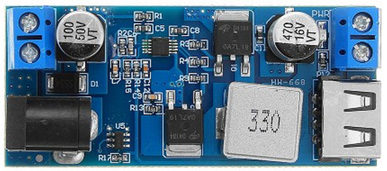
The 24/5V Buck Converter, manufactured by Arduino (Part ID: UNO), is a DC-DC step-down voltage regulator designed to efficiently convert a 24V input to a stable 5V output. This component is ideal for powering low-voltage devices from higher-voltage sources, ensuring minimal heat generation and high efficiency. It is widely used in embedded systems, IoT devices, robotics, and other applications requiring reliable 5V power from a 24V supply.
Explore Projects Built with 24/5v Buck


Explore Projects Built with 24/5v Buck
Common Applications and Use Cases
- Powering microcontrollers (e.g., Arduino boards) and sensors in embedded systems
- Supplying 5V to USB-powered devices from industrial 24V sources
- Robotics and automation systems requiring multiple voltage levels
- Battery-powered systems to step down voltage for low-power components
Technical Specifications
The following table outlines the key technical details of the 24/5V Buck Converter:
| Parameter | Value |
|---|---|
| Input Voltage Range | 18V to 26V |
| Output Voltage | 5V (±2% tolerance) |
| Maximum Output Current | 3A |
| Efficiency | Up to 95% |
| Switching Frequency | 150 kHz |
| Operating Temperature | -40°C to +85°C |
| Dimensions | 25mm x 20mm x 10mm |
Pin Configuration and Descriptions
The 24/5V Buck Converter has four pins for input and output connections:
| Pin Name | Description |
|---|---|
| VIN+ | Positive input voltage (connect to 24V source) |
| VIN- | Negative input voltage (connect to ground of source) |
| VOUT+ | Positive output voltage (5V output) |
| VOUT- | Negative output voltage (connect to ground of load) |
Usage Instructions
How to Use the Component in a Circuit
Connect the Input Voltage:
- Attach the VIN+ pin to the positive terminal of your 24V power source.
- Connect the VIN- pin to the ground terminal of your power source.
Connect the Output Voltage:
- Attach the VOUT+ pin to the positive terminal of the device requiring 5V.
- Connect the VOUT- pin to the ground terminal of the device.
Verify Connections:
- Double-check all connections to ensure proper polarity and avoid short circuits.
Power On:
- Turn on the 24V power source. The buck converter will step down the voltage to 5V and supply it to the connected load.
Important Considerations and Best Practices
- Input Voltage Range: Ensure the input voltage is within the specified range (18V to 26V). Exceeding this range may damage the converter.
- Heat Dissipation: Although the converter is highly efficient, it may generate some heat under high loads. Ensure adequate ventilation or use a heatsink if necessary.
- Load Current: Do not exceed the maximum output current of 3A to prevent overheating or damage.
- Decoupling Capacitors: For improved stability, consider adding decoupling capacitors (e.g., 10µF and 0.1µF) near the input and output terminals.
Example: Using the 24/5V Buck Converter with an Arduino UNO
The following example demonstrates how to power an Arduino UNO using the 24/5V Buck Converter:
Circuit Connections
- Connect the VIN+ and VIN- pins of the buck converter to a 24V DC power source.
- Connect the VOUT+ pin to the 5V pin of the Arduino UNO.
- Connect the VOUT- pin to the GND pin of the Arduino UNO.
Sample Code
// This example demonstrates a simple LED blink program for Arduino UNO
// powered by the 24/5V Buck Converter. Ensure the buck converter is
// properly connected to the Arduino UNO as described in the circuit
// connections section.

void setup() {
  pinMode(13, OUTPUT); // Set pin 13 as an output for the onboard LED
}

void loop() {
  digitalWrite(13, HIGH); // Turn the LED on
  delay(1000);            // Wait for 1 second
  digitalWrite(13, LOW);  // Turn the LED off
  delay(1000);            // Wait for 1 second
}
Troubleshooting and FAQs
Common Issues and Solutions
No Output Voltage:
- Cause: Incorrect wiring or loose connections.
- Solution: Verify all connections and ensure proper polarity.
Overheating:
- Cause: Exceeding the maximum output current or poor ventilation.
- Solution: Reduce the load current or improve ventilation around the converter.
Output Voltage Fluctuations:
- Cause: Insufficient input voltage or unstable power source.
- Solution: Ensure the input voltage is within the specified range and use a stable power source.
Device Not Powering On:
- Cause: Faulty buck converter or incorrect output connections.
- Solution: Test the converter with a multimeter to verify output voltage and check connections.
FAQs
Q1: Can I use the 24/5V Buck Converter with a 12V input?
A1: No, the input voltage must be within the specified range of 18V to 26V for proper operation.
Q2: Is the converter protected against short circuits?
A2: Yes, the converter includes built-in short-circuit protection, but it is recommended to avoid intentional short circuits.
Q3: Can I use this converter to power multiple devices simultaneously?
A3: Yes, as long as the total current draw does not exceed 3A.
Q4: Does the converter require additional components for operation?
A4: No, the converter is a standalone module. However, adding decoupling capacitors can improve stability in some cases.