How to Use DTS33A: Examples, Pinouts, and Specs
Introduction
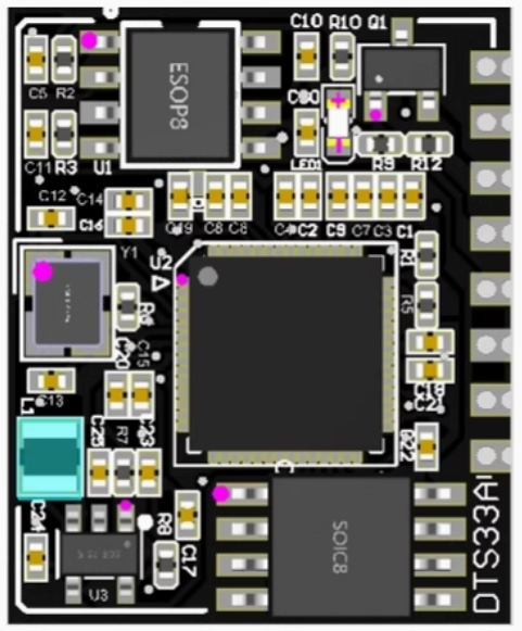
The DTS33A is a precision temperature sensor designed to deliver accurate temperature readings in a compact and reliable package. Its high precision and ease of integration make it a popular choice for a wide range of applications. The DTS33A is commonly used in HVAC systems, industrial equipment, and consumer electronics to monitor and control temperature effectively. Its small form factor and low power consumption make it ideal for both portable and stationary devices.
Explore Projects Built with DTS33A
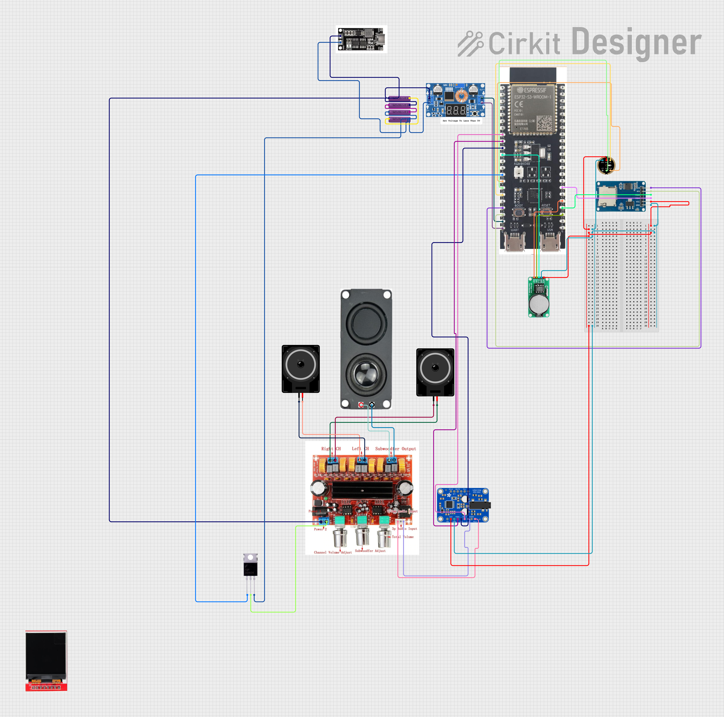
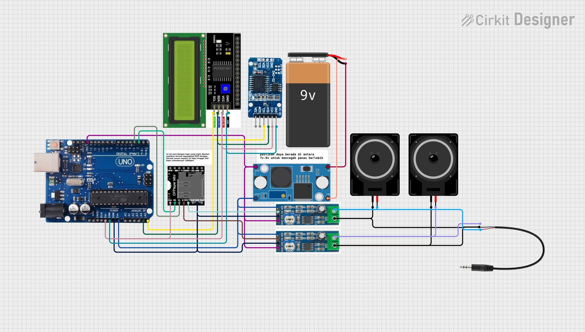

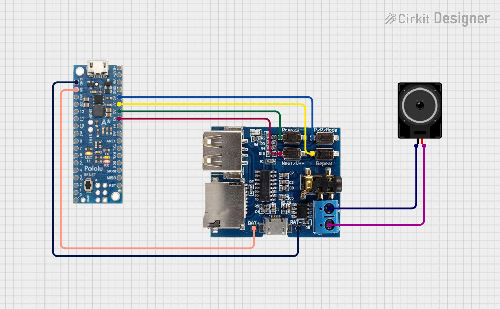
Explore Projects Built with DTS33A
Technical Specifications
The DTS33A is designed to operate efficiently in various environments. Below are its key technical specifications:
| Parameter | Value |
|---|---|
| Operating Voltage | 2.7V to 5.5V |
| Temperature Range | -40°C to +125°C |
| Accuracy | ±0.5°C (typical) |
| Output Type | Digital (I²C interface) |
| Power Consumption | 0.1 mW (typical) |
| Communication Protocol | I²C (7-bit address) |
| Package Type | SOT-23-6 |
Pin Configuration and Descriptions
The DTS33A comes in a 6-pin SOT-23 package. Below is the pinout and description:
| Pin Number | Pin Name | Description |
|---|---|---|
| 1 | VDD | Power supply (2.7V to 5.5V) |
| 2 | GND | Ground connection |
| 3 | SDA | Serial Data Line for I²C communication |
| 4 | SCL | Serial Clock Line for I²C communication |
| 5 | ALERT | Programmable temperature alert output (optional) |
| 6 | NC | No connection (leave unconnected) |
Usage Instructions
To use the DTS33A in a circuit, follow these steps:
- Power Supply: Connect the VDD pin to a stable power source within the range of 2.7V to 5.5V. Connect the GND pin to the ground of the circuit.
- I²C Communication: Connect the SDA and SCL pins to the corresponding I²C lines of your microcontroller. Use pull-up resistors (typically 4.7kΩ) on both lines if not already present in your circuit.
- Alert Pin (Optional): If you wish to use the ALERT pin for temperature threshold notifications, configure it in your microcontroller's firmware.
- Initialization: Initialize the I²C communication in your microcontroller and configure the DTS33A as needed (e.g., set temperature thresholds, read temperature data).
Example: Using DTS33A with Arduino UNO
Below is an example of how to interface the DTS33A with an Arduino UNO using the I²C protocol:
#include <Wire.h>

// DTS33A I²C address (default)
#define DTS33A_ADDRESS 0x48

void setup() {
  Wire.begin(); // Initialize I²C communication
  Serial.begin(9600); // Start serial communication for debugging

  // Optional: Configure DTS33A settings here if needed
  Serial.println("DTS33A Temperature Sensor Initialized");
}

void loop() {
  float temperature = readTemperature();
  Serial.print("Temperature: ");
  Serial.print(temperature);
  Serial.println(" °C");
  delay(1000); // Wait 1 second before the next reading
}

float readTemperature() {
  Wire.beginTransmission(DTS33A_ADDRESS);
  Wire.write(0x00); // Command to read temperature register
  Wire.endTransmission();

  Wire.requestFrom(DTS33A_ADDRESS, 2); // Request 2 bytes of data
  if (Wire.available() == 2) {
    int msb = Wire.read(); // Most significant byte
    int lsb = Wire.read(); // Least significant byte
    int rawTemp = (msb << 8) | lsb; // Combine bytes into a 16-bit value

    // Convert raw temperature to Celsius (assuming 0.01°C/LSB)
    return rawTemp * 0.01;
  } else {
    Serial.println("Error: No data received from DTS33A");
    return -999.0; // Return error value
  }
}
Important Considerations
- Ensure proper pull-up resistors are used on the SDA and SCL lines for reliable I²C communication.
- Avoid placing the DTS33A near heat sources or in direct sunlight, as this may affect its accuracy.
- If using the ALERT pin, configure the temperature thresholds in the DTS33A's internal registers.
Troubleshooting and FAQs
Common Issues
No Data Received from DTS33A
- Cause: Incorrect I²C address or wiring issue.
- Solution: Verify the I²C address (default is 0x48) and check the connections.
Inaccurate Temperature Readings
- Cause: Sensor placed near heat sources or poor thermal contact.
- Solution: Relocate the sensor to a more thermally stable environment.
I²C Communication Fails
- Cause: Missing or incorrect pull-up resistors on SDA/SCL lines.
- Solution: Add 4.7kΩ pull-up resistors to SDA and SCL lines.
FAQs
Can the DTS33A operate at 3.3V?
Yes, the DTS33A operates within a voltage range of 2.7V to 5.5V, making it compatible with 3.3V systems.What is the resolution of the temperature readings?
The DTS33A provides a resolution of 0.01°C per least significant bit (LSB).Is the ALERT pin mandatory to use?
No, the ALERT pin is optional and can be left unconnected if not used.Can the DTS33A be used in battery-powered devices?
Yes, its low power consumption (0.1 mW typical) makes it suitable for battery-powered applications.