How to Use ESP32E: Examples, Pinouts, and Specs
Introduction
The ESP32E by Firebeetle is a versatile and powerful microcontroller that is widely used in the field of Internet of Things (IoT). It is equipped with WiFi and Bluetooth capabilities, allowing for easy wireless communication and data transfer. The dual-core processor and extensive GPIO pin availability make it suitable for a broad range of applications, from simple DIY projects to complex industrial systems.
Explore Projects Built with ESP32E


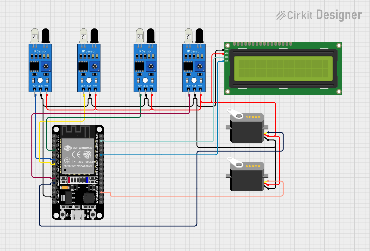
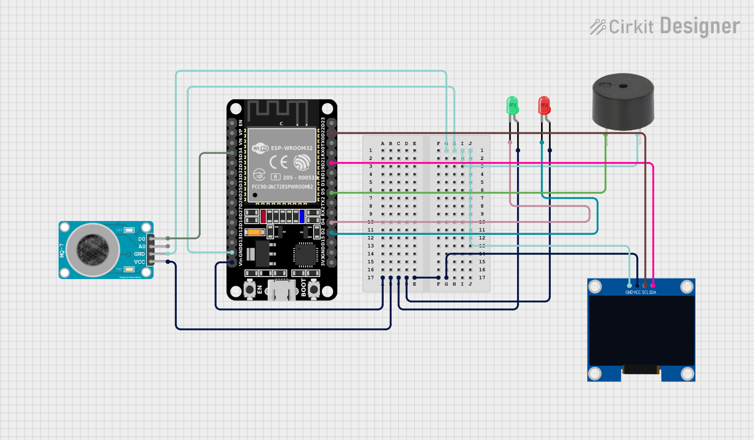
Explore Projects Built with ESP32E
Common Applications and Use Cases
- Smart home devices
- Wireless sensor networks
- IoT gateways
- Wearable electronics
- Remote monitoring and control systems
Technical Specifications
Key Technical Details
- Processor: Tensilica LX6 dual-core processor
- Operating Voltage: 3.3V
- Input Voltage: 3.3V to 7V
- Digital I/O Pins: 34
- Analog Input Pins: 18
- Flash Memory: 4MB
- SRAM: 520 KB
- Clock Speed: Up to 240MHz
- Wi-Fi: 802.11 b/g/n
- Bluetooth: v4.2 BR/EDR and BLE
- Temperature Range: -40°C to +125°C
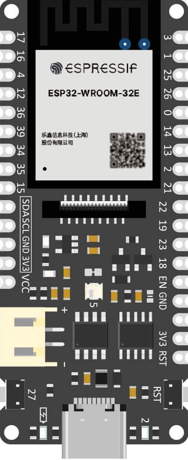
Pin Configuration and Descriptions
| Pin Number | Function | Description |
|---|---|---|
| 1 | 3V3 | Power supply (3.3V) |
| 2 | GND | Ground |
| 3 | EN | Chip enable. Active high. |
| 4 | VP | GPIO36, ADC1_CH0, Sensor VP |
| 5 | VN | GPIO39, ADC1_CH3, Sensor VN |
| ... | ... | ... |
| 36 | IO34 | GPIO34, ADC1_CH6 |
| 37 | IO35 | GPIO35, ADC1_CH7 |
| 38 | IO32 | GPIO32, ADC1_CH4, XTAL_32K_P (32.768 kHz XTAL oscillator input) |
| 39 | IO33 | GPIO33, ADC1_CH5, XTAL_32K_N (32.768 kHz XTAL oscillator output) |
| ... | ... | ... |
Note: This table is not exhaustive. Refer to the ESP32E datasheet for the complete pinout and functions.
Usage Instructions
How to Use the ESP32E in a Circuit
Powering the ESP32E: Connect a 3.3V power supply to the 3V3 and GND pins. Ensure that the power supply can provide sufficient current for the ESP32E and any connected peripherals.
Programming the ESP32E: Use a USB-to-serial converter to connect the ESP32E to a computer. Install the necessary drivers and development environment (e.g., Arduino IDE or ESP-IDF).
Connecting to WiFi: Utilize the onboard WiFi capabilities to connect the ESP32E to a network for internet access or local communication.
Interfacing with Sensors/Devices: Connect sensors or other devices to the GPIO pins, taking care to match the voltage levels and configure the pins correctly in your code.
Important Considerations and Best Practices
- Always ensure that the power supply is within the specified range to prevent damage.
- Use a logic level converter if interfacing with devices that operate at a different voltage.
- When using WiFi or Bluetooth, consider the power consumption and plan for power management strategies if battery operation is required.
- Follow proper ESD precautions when handling the ESP32E to avoid static damage.
Troubleshooting and FAQs
Common Issues
- ESP32E not booting: Check the power supply and connections. Ensure that the EN pin is pulled high.
- WiFi/Bluetooth not functioning: Verify that the antenna is properly connected and that the correct drivers are installed.
- Inconsistent readings from GPIO: Ensure that there is no electrical noise affecting the signals and that the pins are configured correctly.
Solutions and Tips for Troubleshooting
- Use a multimeter to check for proper voltage levels on the power pins.
- Check and re-solder any loose connections or cold solder joints.
- Consult the ESP32E forums and community for support on specific issues.
Example Code for Arduino UNO
Here is a simple example of how to blink an LED connected to the ESP32E using the Arduino IDE:
// Define the LED pin
const int ledPin = 2; // Use GPIO2 for the LED

// Setup function runs once at the start
void setup() {
  // Initialize the LED pin as an output
  pinMode(ledPin, OUTPUT);
}

// Loop function runs over and over again forever
void loop() {
  digitalWrite(ledPin, HIGH);   // Turn the LED on
  delay(1000);                  // Wait for a second
  digitalWrite(ledPin, LOW);    // Turn the LED off
  delay(1000);                  // Wait for a second
}
Note: Before uploading the code, select the correct board (ESP32 Dev Module) and port in the Arduino IDE.
Remember to wrap your code comments appropriately to maintain readability and adhere to the 80 character line length limit.