How to Use Ignition Coil Pin: Examples, Pinouts, and Specs
Introduction
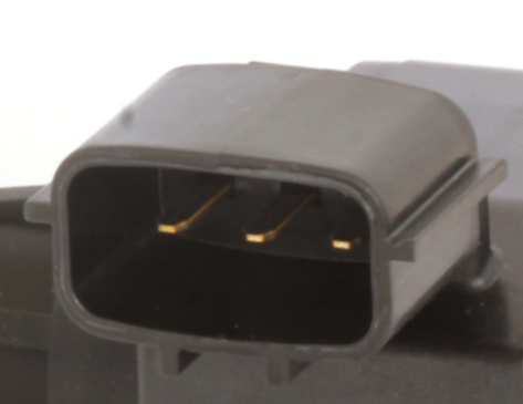
The Ignition Coil Pin, manufactured by Central Automotive Products Ltd., is a crucial part of the ignition coil system in internal combustion engines. This component is responsible for transferring electrical energy to the spark plug, which ignites the air-fuel mixture in the engine's cylinders. Proper functioning of the ignition coil pin is essential for the efficient operation of the engine, ensuring smooth starts and optimal performance.
Explore Projects Built with Ignition Coil Pin
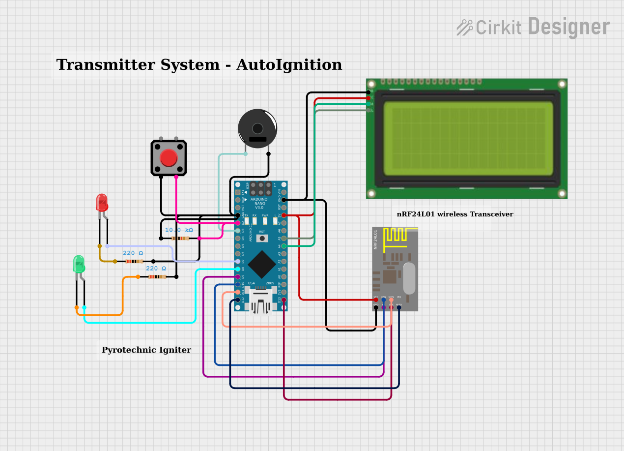

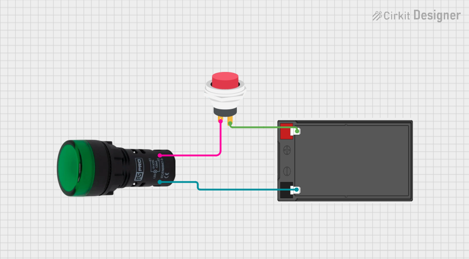

Explore Projects Built with Ignition Coil Pin
Common Applications and Use Cases
- Automotive Engines: Used in cars, motorcycles, and other vehicles with internal combustion engines.
- Small Engines: Found in lawnmowers, chainsaws, and other small machinery.
- Generators: Utilized in portable and standby generators.
- Marine Engines: Employed in boat engines and other marine applications.
Technical Specifications
The following table provides key technical details for the Ignition Coil Pin:
| Parameter | Specification |
|---|---|
| Manufacturer | Central Automotive Products Ltd. |
| Part ID | Ignition Coil |
| Voltage Rating | 12V |
| Current Rating | 5A |
| Power Rating | 60W |
| Material | High-grade steel |
| Insulation | High-temperature resistant plastic |
| Operating Temperature Range | -40°C to 125°C |
| Dimensions | 50mm x 10mm x 10mm |
| Weight | 15g |
Pin Configuration and Descriptions
| Pin Number | Description |
|---|---|
| 1 | Primary Coil Input (Positive) |
| 2 | Primary Coil Input (Negative) |
| 3 | Secondary Coil Output (High Voltage) |
| 4 | Ground |
Usage Instructions
How to Use the Component in a Circuit
- Identify the Pins: Refer to the pin configuration table to identify the correct pins for connection.
- Connect the Primary Coil Inputs: Connect Pin 1 to the positive terminal of the power source (typically 12V) and Pin 2 to the negative terminal (ground).
- Connect the Secondary Coil Output: Connect Pin 3 to the spark plug. Ensure that the connection is secure and insulated to handle high voltage.
- Ground the Component: Connect Pin 4 to the engine block or chassis ground.
Important Considerations and Best Practices
- Ensure Proper Insulation: High voltage is generated at the secondary coil output. Use appropriate insulation to prevent electrical shocks and short circuits.
- Check Connections: Regularly inspect connections for corrosion or wear, which can affect performance.
- Avoid Overheating: Ensure the component is not exposed to temperatures beyond its operating range to prevent damage.
- Use Compatible Components: Ensure that the ignition coil pin is compatible with the ignition coil and spark plug used in your application.
Troubleshooting and FAQs
Common Issues Users Might Face
No Spark at the Spark Plug:
- Solution: Check the connections to ensure they are secure and free of corrosion. Verify that the power source is providing the correct voltage.
Intermittent Spark:
- Solution: Inspect the ignition coil pin for signs of wear or damage. Ensure that the insulation is intact and that there are no loose connections.
Overheating:
- Solution: Ensure that the component is not exposed to temperatures beyond its operating range. Check for proper ventilation and cooling in the engine compartment.
FAQs
Q: Can the Ignition Coil Pin be used with any ignition coil? A: The Ignition Coil Pin is designed to be compatible with most standard ignition coils. However, it is recommended to verify compatibility with the specific ignition coil used in your application.
Q: How often should the Ignition Coil Pin be replaced? A: The Ignition Coil Pin should be inspected regularly for signs of wear or damage. Replacement intervals can vary based on usage and operating conditions, but it is generally recommended to replace it as part of routine engine maintenance.
Q: What should I do if the Ignition Coil Pin fails? A: If the Ignition Coil Pin fails, it should be replaced immediately to ensure proper engine operation. Follow the usage instructions to install a new pin and verify that all connections are secure.
Example Code for Arduino UNO
If you are using the Ignition Coil Pin in a project with an Arduino UNO, the following example code demonstrates how to control the ignition coil using a digital output pin.
// Example code to control an ignition coil using Arduino UNO

const int ignitionPin = 7; // Digital pin connected to the ignition coil

void setup() {
  pinMode(ignitionPin, OUTPUT); // Set the ignition pin as an output
}

void loop() {
  digitalWrite(ignitionPin, HIGH); // Turn on the ignition coil
  delay(1000); // Keep it on for 1 second
  digitalWrite(ignitionPin, LOW); // Turn off the ignition coil
  delay(1000); // Keep it off for 1 second
}
In this example, the ignition coil is turned on and off every second. Adjust the delay values as needed for your specific application.
This documentation provides a comprehensive overview of the Ignition Coil Pin, including its technical specifications, usage instructions, troubleshooting tips, and example code for integration with an Arduino UNO. Whether you are a beginner or an experienced user, this guide will help you effectively utilize the Ignition Coil Pin in your projects.