How to Use BLDC Motor: Examples, Pinouts, and Specs
Introduction
The StepperOnline 57BLR50-24-01 is a high-performance Brushless DC (BLDC) motor designed for applications requiring efficiency, reliability, and low maintenance. Unlike traditional brushed motors, the BLDC motor uses electronic commutation to eliminate the need for brushes, resulting in reduced wear and tear, quieter operation, and improved lifespan.
Explore Projects Built with BLDC Motor
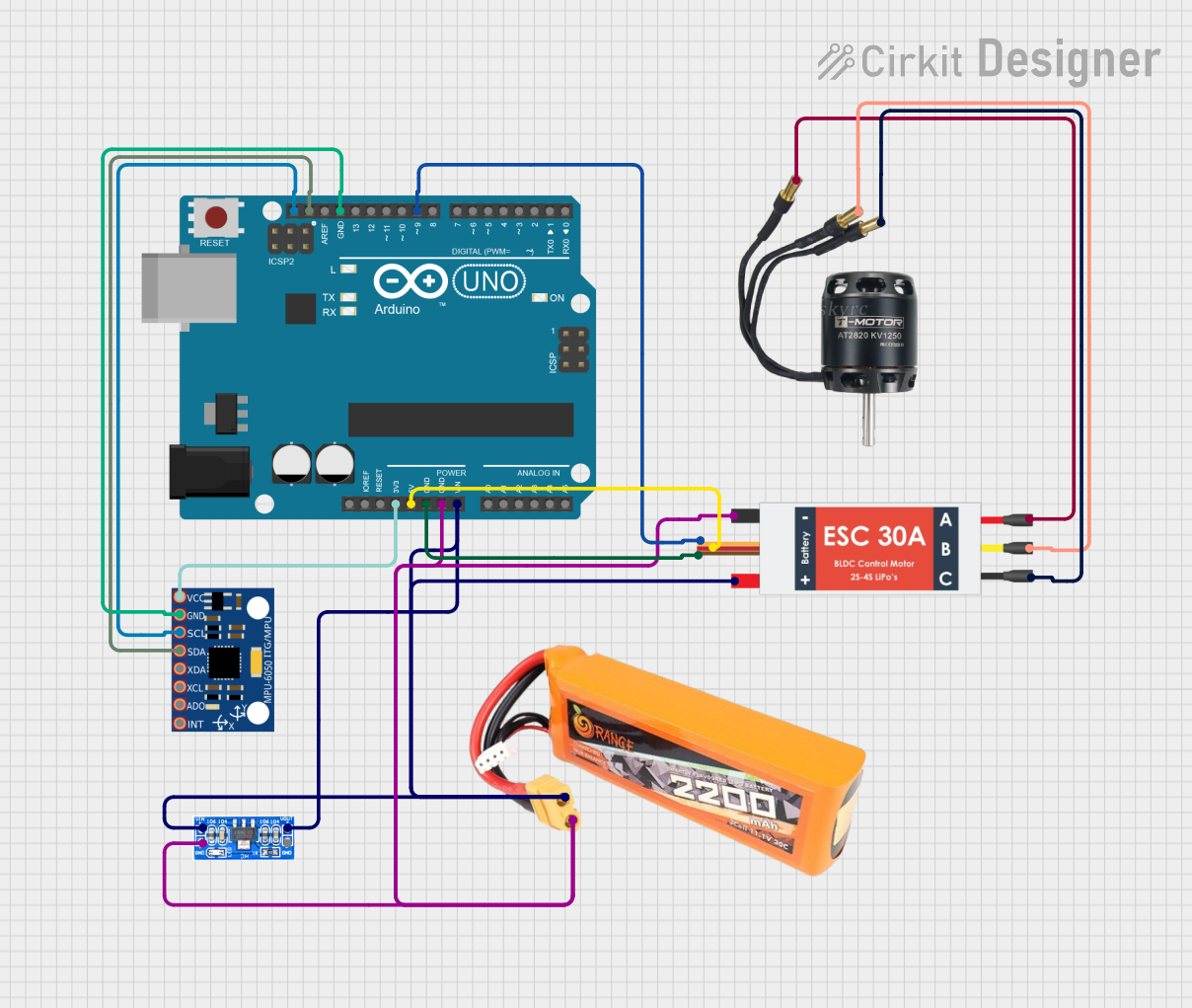
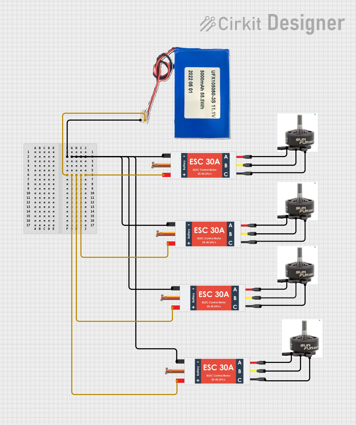

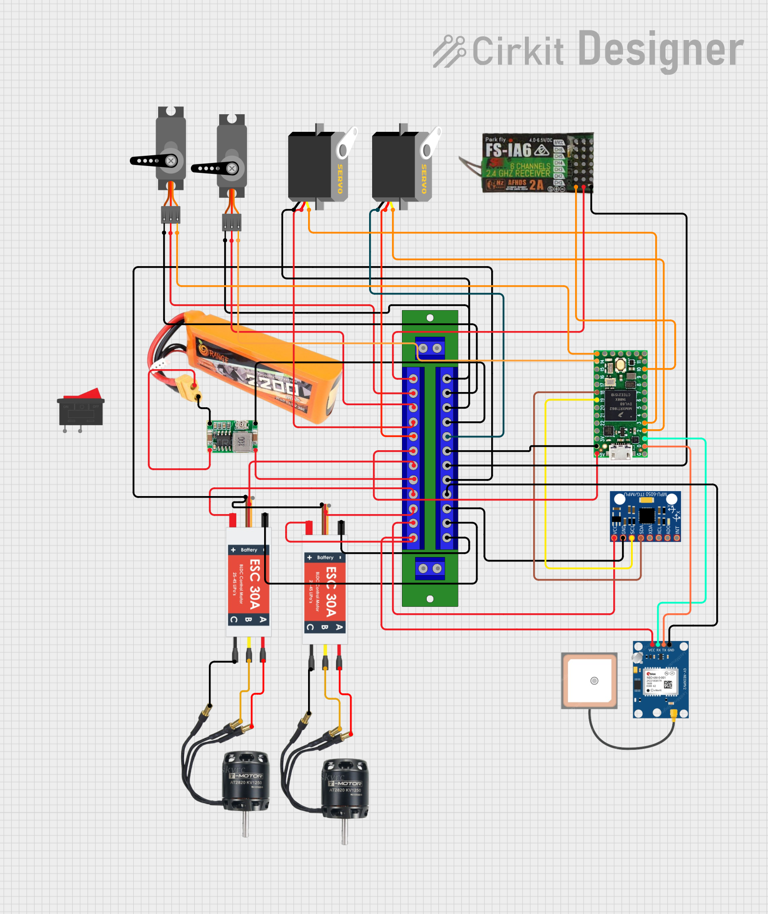
Explore Projects Built with BLDC Motor
Common Applications
- Robotics and automation systems
- Electric vehicles (EVs) and drones
- Industrial machinery and conveyor systems
- HVAC systems and pumps
- Medical devices and precision instruments
Technical Specifications
The following table outlines the key technical specifications of the StepperOnline 57BLR50-24-01 BLDC motor:
| Parameter | Value |
|---|---|
| Manufacturer | StepperOnline |
| Part Number | 57BLR50-24-01 |
| Motor Type | Brushless DC (BLDC) |
| Rated Voltage | 24 V DC |
| Rated Speed | 4000 RPM |
| Rated Torque | 0.57 Nm |
| Rated Power | 240 W |
| Number of Poles | 8 |
| Rotor Inertia | 120 g·cm² |
| Phase Resistance | 0.57 Ω |
| Phase Inductance | 1.2 mH |
| Weight | 1.2 kg |
Pin Configuration and Descriptions
The 57BLR50-24-01 BLDC motor typically has three main phase wires and optional sensor wires for feedback. The pinout is as follows:
Motor Phase Wires
| Wire Color | Function | Description |
|---|---|---|
| Red | Phase A | Connects to the motor driver for phase A |
| Yellow | Phase B | Connects to the motor driver for phase B |
| Blue | Phase C | Connects to the motor driver for phase C |
Hall Sensor Wires (Optional)
| Wire Color | Function | Description |
|---|---|---|
| Black | Ground (GND) | Common ground for Hall sensors |
| Red | Vcc (5V) | Power supply for Hall sensors |
| Green | Hall Sensor A | Outputs signal for rotor position (Phase A) |
| Yellow | Hall Sensor B | Outputs signal for rotor position (Phase B) |
| Blue | Hall Sensor C | Outputs signal for rotor position (Phase C) |
Usage Instructions
How to Use the BLDC Motor in a Circuit
Connect the Motor to a Driver:
Use a compatible BLDC motor driver or controller to manage the motor's operation. Ensure the driver supports the motor's voltage and current ratings.Power Supply:
Provide a stable 24 V DC power supply to the motor driver. Ensure the power supply can handle the motor's rated current.Phase Connections:
Connect the motor's phase wires (Red, Yellow, Blue) to the corresponding outputs on the motor driver.Hall Sensor Connections (if applicable):
- Connect the Hall sensor wires to the driver or microcontroller for feedback.
- Ensure the Vcc and GND connections are correct to avoid damaging the sensors.
Control Signals:
Use a microcontroller (e.g., Arduino UNO) or other control systems to send PWM or other control signals to the motor driver.
Important Considerations
- Driver Compatibility: Always use a motor driver compatible with BLDC motors and the motor's specifications.
- Heat Dissipation: Ensure proper ventilation or heat sinks to prevent overheating during operation.
- Startup Sequence: BLDC motors require a specific startup sequence for proper commutation. Use a driver that handles this automatically.
- Load Conditions: Avoid overloading the motor beyond its rated torque to prevent damage.
Example: Controlling the BLDC Motor with Arduino UNO
Below is an example of how to control the 57BLR50-24-01 BLDC motor using an Arduino UNO and a compatible motor driver:
// Example: Controlling a BLDC motor with Arduino UNO
// Ensure the motor driver supports PWM control and is connected properly

const int pwmPin = 9;  // PWM signal pin connected to motor driver
const int dirPin = 8;  // Direction control pin connected to motor driver

void setup() {
  pinMode(pwmPin, OUTPUT);  // Set PWM pin as output
  pinMode(dirPin, OUTPUT);  // Set direction pin as output

  digitalWrite(dirPin, HIGH);  // Set initial direction (HIGH = forward)
}

void loop() {
  // Gradually increase motor speed
  for (int speed = 0; speed <= 255; speed++) {
    analogWrite(pwmPin, speed);  // Send PWM signal to motor driver
    delay(20);                   // Wait for 20 ms
  }

  delay(2000);  // Run at full speed for 2 seconds

  // Gradually decrease motor speed
  for (int speed = 255; speed >= 0; speed--) {
    analogWrite(pwmPin, speed);  // Reduce PWM signal
    delay(20);                   // Wait for 20 ms
  }

  delay(2000);  // Stop for 2 seconds before repeating
}
Troubleshooting and FAQs
Common Issues and Solutions
Motor Does Not Start
- Cause: Incorrect wiring or insufficient power supply.
- Solution: Double-check all connections and ensure the power supply meets the motor's requirements.
Motor Vibrates but Does Not Rotate
- Cause: Incorrect phase wiring or commutation issues.
- Solution: Verify the phase connections (Red, Yellow, Blue) and ensure the driver is configured correctly.
Overheating
- Cause: Prolonged operation at high loads or insufficient cooling.
- Solution: Reduce the load or improve heat dissipation with a heat sink or fan.
Hall Sensor Malfunction
- Cause: Incorrect wiring or damaged sensors.
- Solution: Check the Hall sensor connections and replace damaged sensors if necessary.
FAQs
Q: Can I run the motor without a Hall sensor?
A: Yes, but sensorless operation requires a driver capable of estimating rotor position. This may reduce performance at low speeds.
Q: What type of driver is recommended for this motor?
A: Use a BLDC motor driver that supports 24 V DC and can handle the motor's rated current and power.
Q: How do I reverse the motor's direction?
A: Change the direction control signal on the motor driver or swap any two phase wires (not recommended for Hall sensor configurations).
Q: Can I use this motor for high-precision applications?
A: Yes, when paired with a suitable driver and feedback system, the motor can achieve high precision.