How to Use ESP-WROOM-32-cpu-front: Examples, Pinouts, and Specs
Introduction
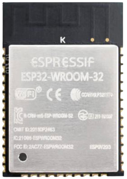
The ESP-WROOM-32 is a powerful Wi-Fi and Bluetooth module designed for IoT (Internet of Things) applications. It integrates a dual-core processor, offering high performance and versatility for a wide range of projects. This module is known for its low power consumption, extensive GPIO pin availability, and support for multiple communication protocols, making it a popular choice for developers and hobbyists alike.
Explore Projects Built with ESP-WROOM-32-cpu-front

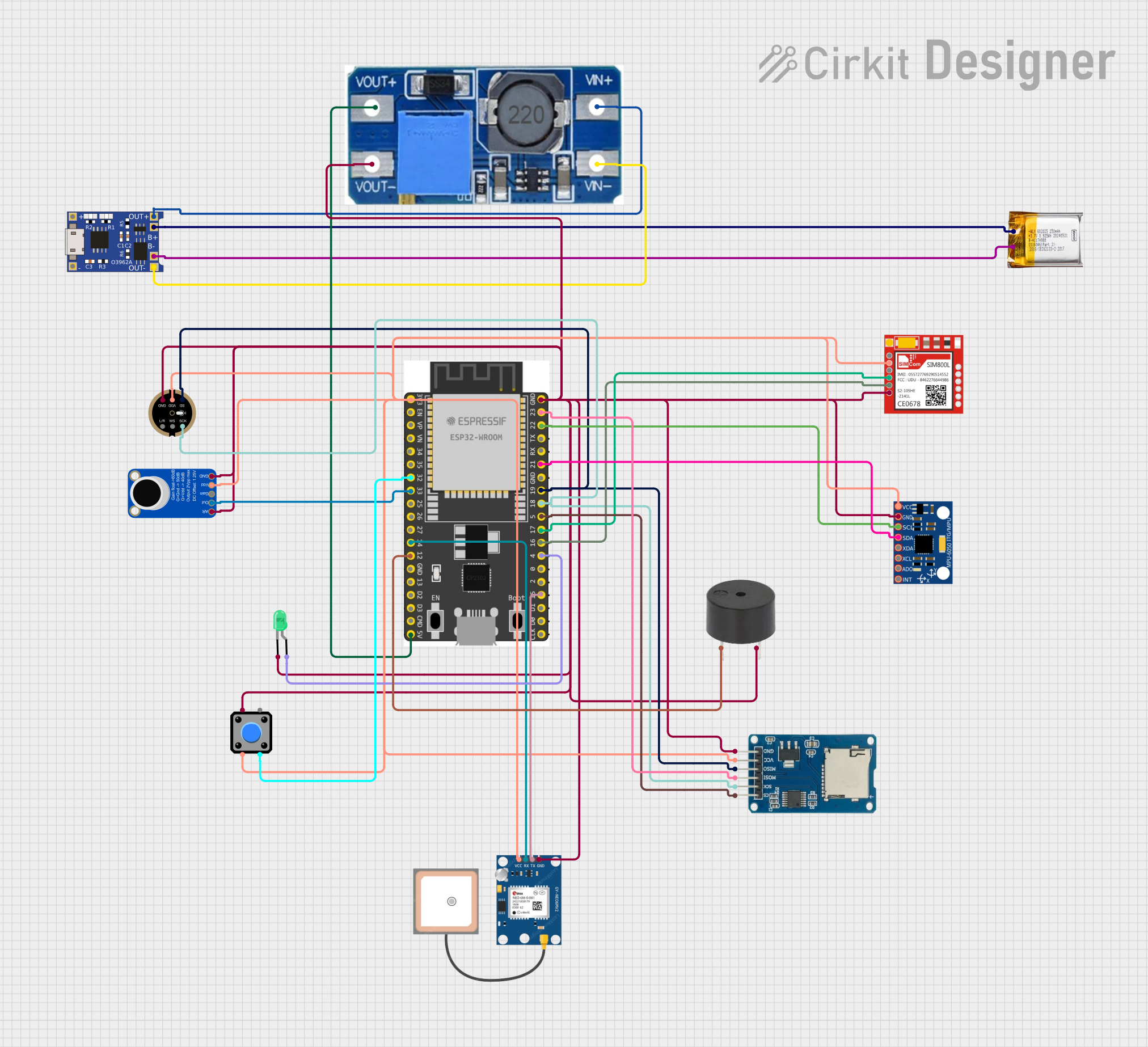
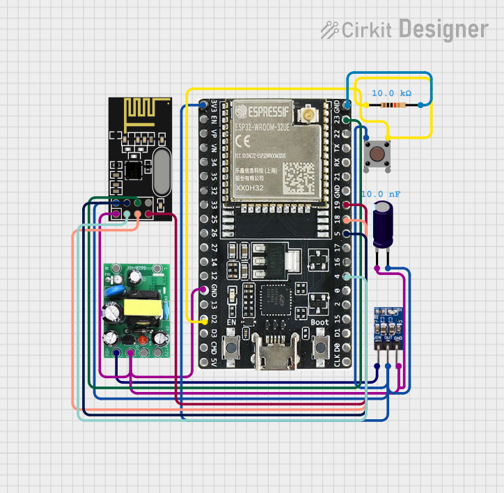

Explore Projects Built with ESP-WROOM-32-cpu-front
Common Applications and Use Cases
- Smart home devices (e.g., smart lights, thermostats)
- Wearable technology
- Industrial automation
- Wireless sensor networks
- IoT gateways and hubs
- Prototyping and development of connected devices
Technical Specifications
Key Technical Details
- Processor: Dual-core Xtensa® 32-bit LX6 CPU
- Clock Speed: Up to 240 MHz
- Flash Memory: 4 MB (default, can vary by model)
- RAM: 520 KB SRAM
- Wi-Fi: 802.11 b/g/n (2.4 GHz)
- Bluetooth: v4.2 BR/EDR and BLE
- Operating Voltage: 3.0V to 3.6V
- Power Consumption: Ultra-low power (varies by mode)
- GPIO Pins: 34 (multipurpose, including ADC, DAC, PWM, I2C, SPI, UART)
- Operating Temperature: -40°C to +85°C
- Dimensions: 18 mm x 25.5 mm x 3.1 mm
Pin Configuration and Descriptions
The ESP-WROOM-32 module has 38 pins, but not all are available for general use. Below is a table of key pins and their functions:
| Pin Number | Pin Name | Function |
|---|---|---|
| 1 | EN | Enable pin. Active high. Used to reset the module. |
| 2 | IO0 | GPIO0. Can be used for general I/O or boot mode selection. |
| 3 | IO2 | GPIO2. General-purpose I/O. |
| 4 | IO4 | GPIO4. General-purpose I/O. |
| 5 | IO5 | GPIO5. General-purpose I/O. |
| 6 | IO12 | GPIO12. Can be used as ADC2 or general-purpose I/O. |
| 7 | IO13 | GPIO13. Can be used as ADC2 or general-purpose I/O. |
| 8 | IO14 | GPIO14. Can be used as ADC2 or general-purpose I/O. |
| 9 | IO15 | GPIO15. Can be used as ADC2 or general-purpose I/O. |
| 10 | IO16 | GPIO16. General-purpose I/O. |
| 11 | IO17 | GPIO17. General-purpose I/O. |
| 12 | IO18 | GPIO18. SPI clock or general-purpose I/O. |
| 13 | IO19 | GPIO19. SPI MISO or general-purpose I/O. |
| 14 | IO21 | GPIO21. I2C SDA or general-purpose I/O. |
| 15 | IO22 | GPIO22. I2C SCL or general-purpose I/O. |
| 16 | IO23 | GPIO23. SPI MOSI or general-purpose I/O. |
| 17 | GND | Ground. Connect to the ground of the power supply. |
| 18 | 3V3 | 3.3V power input. |
Note: Some GPIO pins have specific restrictions or are used during boot. Refer to the ESP32 datasheet for detailed pin behavior.
Usage Instructions
How to Use the ESP-WROOM-32 in a Circuit
- Power Supply: Provide a stable 3.3V power supply to the
3V3pin. Ensure the ground (GND) is connected to the circuit's ground. - Boot Mode: To upload code, connect GPIO0 to ground during reset. For normal operation, leave GPIO0 unconnected or pull it high.
- Programming: Use a USB-to-serial adapter (e.g., FTDI or CP2102) to connect the module to your computer. Connect the following:
- TX of the adapter to RX of the ESP-WROOM-32
- RX of the adapter to TX of the ESP-WROOM-32
- GND of the adapter to GND of the ESP-WROOM-32
- Communication Protocols: Use the appropriate pins for I2C, SPI, UART, or PWM as needed for your application.
Important Considerations and Best Practices
- Voltage Levels: The ESP-WROOM-32 operates at 3.3V. Do not expose GPIO pins to 5V signals.
- Antenna Placement: Ensure the onboard antenna has sufficient clearance from metal objects to avoid signal interference.
- Heat Management: If operating at high loads, consider adding a heatsink or ensuring proper ventilation.
- Firmware Updates: Keep the firmware updated to the latest version for improved performance and security.
Example: Connecting to an Arduino UNO
The ESP-WROOM-32 can be used with an Arduino UNO for Wi-Fi or Bluetooth functionality. Below is an example of connecting the ESP-WROOM-32 to an Arduino UNO and uploading a basic Wi-Fi scan sketch.
Wiring Diagram
| Arduino UNO Pin | ESP-WROOM-32 Pin |
|---|---|
| 3.3V | 3V3 |
| GND | GND |
| TX | RX |
| RX | TX |
Code Example
#include <WiFi.h> // Include the Wi-Fi library for ESP32

void setup() {
  Serial.begin(115200); // Initialize serial communication
  WiFi.mode(WIFI_STA);  // Set Wi-Fi mode to station
  WiFi.disconnect();    // Disconnect from any previous connections
  delay(100);

  Serial.println("Starting Wi-Fi scan...");
  int n = WiFi.scanNetworks(); // Scan for available networks
  Serial.println("Scan complete.");

  if (n == 0) {
    Serial.println("No networks found.");
  } else {
    Serial.println("Networks found:");
    for (int i = 0; i < n; ++i) {
      // Print SSID and signal strength of each network
      Serial.print(i + 1);
      Serial.print(": ");
      Serial.print(WiFi.SSID(i));
      Serial.print(" (");
      Serial.print(WiFi.RSSI(i));
      Serial.println(" dBm)");
    }
  }
}

void loop() {
  // Nothing to do here
}
Note: Ensure the ESP-WROOM-32 is in programming mode when uploading the sketch.
Troubleshooting and FAQs
Common Issues
- Module Not Responding:
- Ensure the power supply is stable and provides sufficient current (at least 500 mA).
- Check the connections, especially TX and RX lines.
- Wi-Fi Not Connecting:
- Verify the SSID and password.
- Ensure the router is operating on the 2.4 GHz band (ESP-WROOM-32 does not support 5 GHz).
- Upload Fails:
- Ensure GPIO0 is grounded during reset for programming mode.
- Check the USB-to-serial adapter drivers on your computer.
Solutions and Tips for Troubleshooting
- Use a multimeter to verify voltage levels on the
3V3andGNDpins. - If the module overheats, reduce the clock speed or optimize your code to reduce processing load.
- For debugging, use the
Serial.print()function to output messages to the serial monitor.
By following this documentation, you can effectively integrate the ESP-WROOM-32 into your projects and troubleshoot common issues.