Cirkit Designer Logo
Cirkit Designer
Your all-in-one circuit design IDE
Home / 
Component Documentation

How to Use HiLetGo ESP32-WROOM-32D: Examples, Pinouts, and Specs

Image of HiLetGo ESP32-WROOM-32D
Cirkit Designer LogoDesign with HiLetGo ESP32-WROOM-32D in Cirkit Designer

Introduction

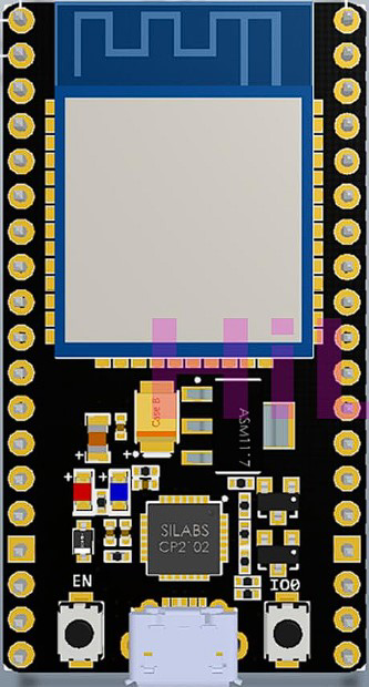
The HiLetGo ESP32-WROOM-32D (Part ID: 3-01-1287) is a high-performance microcontroller module designed for IoT (Internet of Things) applications. It features integrated Wi-Fi and Bluetooth capabilities, a dual-core processor, and a wide range of GPIO pins, making it suitable for projects requiring wireless communication, real-time processing, and versatile interfacing.

Explore Projects Built with HiLetGo ESP32-WROOM-32D

Use Cirkit Designer to design, explore, and prototype these projects online. Some projects support real-time simulation. Click "Open Project" to start designing instantly!
ESP32-Based GPS Tracker with SD Card Logging and Barometric Sensor
Image of gps projekt circuit: A project utilizing HiLetGo ESP32-WROOM-32D in a practical application
This circuit features an ESP32 Wroom Dev Kit as the main microcontroller, interfaced with an MPL3115A2 sensor for pressure and temperature readings, and a Neo 6M GPS module for location tracking. The ESP32 is also connected to an SD card reader for data logging purposes. A voltage regulator is used to step down the USB power supply to 3.3V, which powers the ESP32, the sensor, and the SD card reader.
Cirkit Designer LogoOpen Project in Cirkit Designer
ESP32-Based Environmental and Magnetic Field Monitoring System with OLED Display
Image of nam: A project utilizing HiLetGo ESP32-WROOM-32D in a practical application
This circuit features an ESP32 microcontroller connected to a DHT11 temperature and humidity sensor, two Hall effect sensors for detecting magnetic fields, an OLED display for output, and a buzzer for audible alerts. The ESP32 reads temperature and humidity data from the DHT11 sensor and magnetic field data from the Hall sensors, displaying the information on the OLED screen and potentially triggering the buzzer based on certain conditions. The ESP32 manages power distribution to the sensors and the display, and communicates with the OLED via I2C (SCL and SDA lines connected to pins 22 and 21 respectively).
Cirkit Designer LogoOpen Project in Cirkit Designer
ESP32-Based Multi-Sensor Health Monitoring System with Bluetooth Connectivity
Image of circuit diagram: A project utilizing HiLetGo ESP32-WROOM-32D in a practical application
This circuit features an ESP32-WROOM-32UE microcontroller as the central processing unit, interfacing with a variety of sensors and modules. It includes a MAX30100 pulse oximeter and heart-rate sensor, an MLX90614 infrared thermometer, an HC-05 Bluetooth module for wireless communication, and a Neo 6M GPS module for location tracking. All components are powered by a common voltage supply and are connected to specific GPIO pins on the ESP32 for data exchange, with the sensors using I2C communication and the modules using UART.
Cirkit Designer LogoOpen Project in Cirkit Designer
ESP32-Based Vibration Motor Controller with I2C IO Expansion
Image of VIBRATYION: A project utilizing HiLetGo ESP32-WROOM-32D in a practical application
This circuit features an ESP32 Wroom Dev Kit microcontroller interfaced with an MCP23017 I/O expansion board via I2C communication, utilizing GPIO 21 and GPIO 22 for SDA and SCL lines, respectively. A vibration motor is controlled by an NPN transistor acting as a switch, with a diode for back EMF protection and a resistor to limit base current. The ESP32 can control the motor by sending signals to the MCP23017, which then interfaces with the transistor to turn the motor on or off.
Cirkit Designer LogoOpen Project in Cirkit Designer

Explore Projects Built with HiLetGo ESP32-WROOM-32D

Use Cirkit Designer to design, explore, and prototype these projects online. Some projects support real-time simulation. Click "Open Project" to start designing instantly!
Image of gps projekt circuit: A project utilizing HiLetGo ESP32-WROOM-32D in a practical application
ESP32-Based GPS Tracker with SD Card Logging and Barometric Sensor
This circuit features an ESP32 Wroom Dev Kit as the main microcontroller, interfaced with an MPL3115A2 sensor for pressure and temperature readings, and a Neo 6M GPS module for location tracking. The ESP32 is also connected to an SD card reader for data logging purposes. A voltage regulator is used to step down the USB power supply to 3.3V, which powers the ESP32, the sensor, and the SD card reader.
Cirkit Designer LogoOpen Project in Cirkit Designer
Image of nam: A project utilizing HiLetGo ESP32-WROOM-32D in a practical application
ESP32-Based Environmental and Magnetic Field Monitoring System with OLED Display
This circuit features an ESP32 microcontroller connected to a DHT11 temperature and humidity sensor, two Hall effect sensors for detecting magnetic fields, an OLED display for output, and a buzzer for audible alerts. The ESP32 reads temperature and humidity data from the DHT11 sensor and magnetic field data from the Hall sensors, displaying the information on the OLED screen and potentially triggering the buzzer based on certain conditions. The ESP32 manages power distribution to the sensors and the display, and communicates with the OLED via I2C (SCL and SDA lines connected to pins 22 and 21 respectively).
Cirkit Designer LogoOpen Project in Cirkit Designer
Image of circuit diagram: A project utilizing HiLetGo ESP32-WROOM-32D in a practical application
ESP32-Based Multi-Sensor Health Monitoring System with Bluetooth Connectivity
This circuit features an ESP32-WROOM-32UE microcontroller as the central processing unit, interfacing with a variety of sensors and modules. It includes a MAX30100 pulse oximeter and heart-rate sensor, an MLX90614 infrared thermometer, an HC-05 Bluetooth module for wireless communication, and a Neo 6M GPS module for location tracking. All components are powered by a common voltage supply and are connected to specific GPIO pins on the ESP32 for data exchange, with the sensors using I2C communication and the modules using UART.
Cirkit Designer LogoOpen Project in Cirkit Designer
Image of VIBRATYION: A project utilizing HiLetGo ESP32-WROOM-32D in a practical application
ESP32-Based Vibration Motor Controller with I2C IO Expansion
This circuit features an ESP32 Wroom Dev Kit microcontroller interfaced with an MCP23017 I/O expansion board via I2C communication, utilizing GPIO 21 and GPIO 22 for SDA and SCL lines, respectively. A vibration motor is controlled by an NPN transistor acting as a switch, with a diode for back EMF protection and a resistor to limit base current. The ESP32 can control the motor by sending signals to the MCP23017, which then interfaces with the transistor to turn the motor on or off.
Cirkit Designer LogoOpen Project in Cirkit Designer

Common Applications and Use Cases

  • IoT devices and smart home automation
  • Wireless sensor networks
  • Robotics and real-time control systems
  • Wearable devices
  • Data logging and remote monitoring
  • Prototyping and development of connected devices

Technical Specifications

Key Technical Details

Parameter Specification
Manufacturer HiLetGo
Part ID 3-01-1287
Microcontroller ESP32-D0WDQ6 (dual-core Xtensa LX6)
Clock Speed Up to 240 MHz
Flash Memory 4 MB
SRAM 520 KB
Wireless Connectivity Wi-Fi 802.11 b/g/n, Bluetooth v4.2
Operating Voltage 3.3V
Input Voltage Range 3.0V - 3.6V
GPIO Pins 36
Communication Protocols UART, SPI, I2C, I2S, PWM, ADC, DAC
ADC Resolution 12-bit
DAC Resolution 8-bit
Operating Temperature -40°C to +85°C
Dimensions 25.5 mm x 18 mm x 3 mm

Pin Configuration and Descriptions

The HiLetGo ESP32-WROOM-32D has 38 pins. Below is a summary of the key pins and their functions:

Pin Number Name Function Description
1 EN Enable pin. Active high to enable the module.
2 IO0 GPIO0, used for boot mode selection.
3 IO1 (TX0) GPIO1, UART0 TX pin.
4 IO3 (RX0) GPIO3, UART0 RX pin.
5 IO4 GPIO4, general-purpose I/O.
6 IO5 GPIO5, general-purpose I/O.
7 IO12 GPIO12, supports ADC2 and touch sensing.
8 IO13 GPIO13, supports ADC2 and touch sensing.
9 IO14 GPIO14, supports ADC2 and touch sensing.
10 IO15 GPIO15, supports ADC2 and touch sensing.
11 IO16 GPIO16, general-purpose I/O.
12 IO17 GPIO17, general-purpose I/O.
13 IO18 GPIO18, supports SPI clock (SCK).
14 IO19 GPIO19, supports SPI data (MISO).
15 IO21 GPIO21, supports I2C SDA.
16 IO22 GPIO22, supports I2C SCL.
17 IO23 GPIO23, supports SPI data (MOSI).
18 GND Ground pin.
19 3V3 3.3V power output.

Note: Some GPIO pins have specific restrictions or dual functions. Refer to the ESP32 datasheet for detailed pin behavior.

Usage Instructions

How to Use the Component in a Circuit

  1. Powering the Module:

    • Provide a stable 3.3V power supply to the 3V3 pin. Avoid exceeding the input voltage range (3.0V - 3.6V).
    • Connect the GND pin to the ground of your circuit.
  2. Programming the Module:

    • Use a USB-to-Serial adapter to connect the ESP32 to your computer.
    • Connect the TX pin of the adapter to the RX0 pin (IO3) of the ESP32.
    • Connect the RX pin of the adapter to the TX0 pin (IO1) of the ESP32.
    • Use the EN pin to reset the module if needed.
  3. Boot Mode Selection:

    • To upload code, hold the IO0 pin low (connect to GND) while resetting the module.
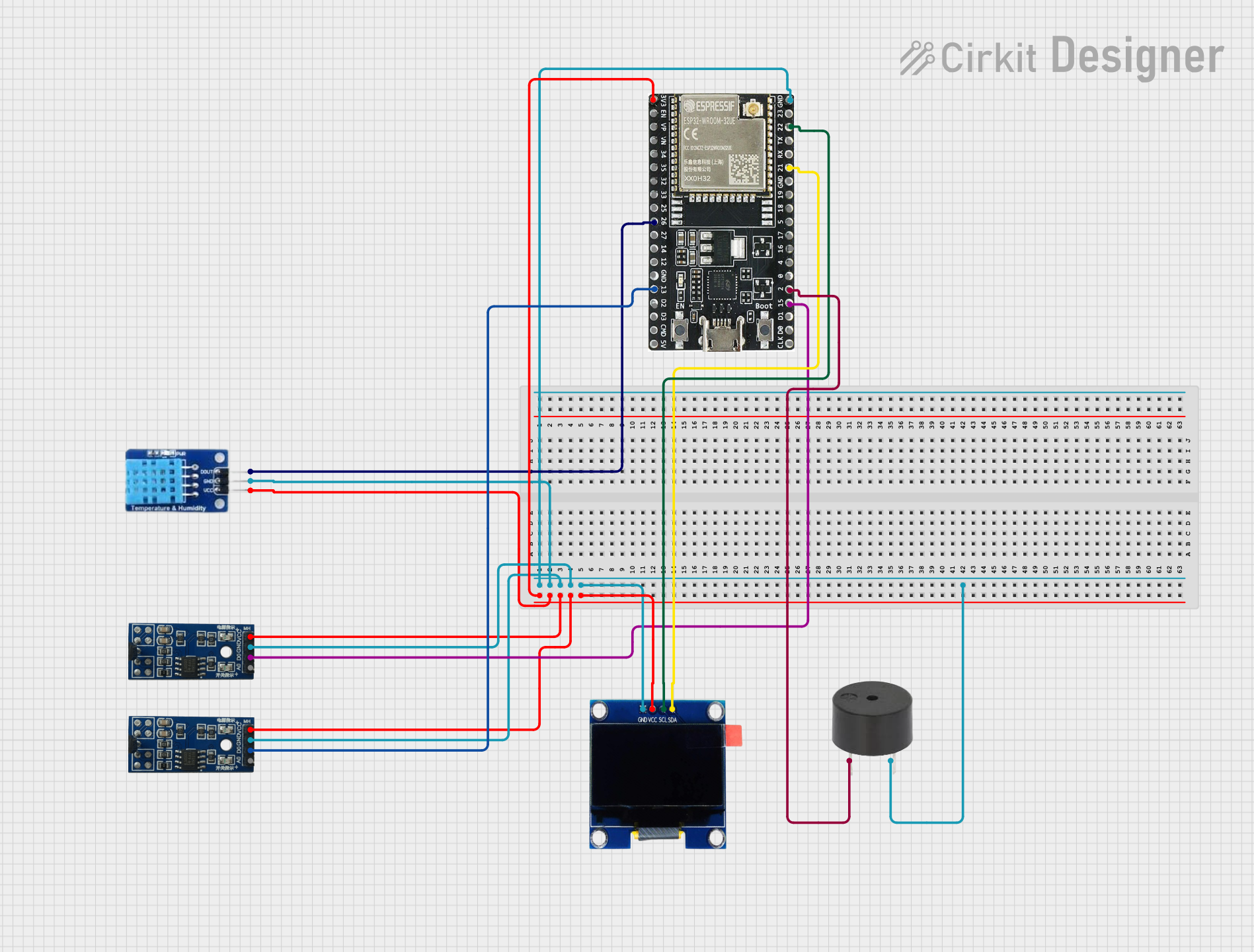
  4. Connecting Peripherals:

    • Use GPIO pins for interfacing with sensors, actuators, and other devices.
    • For I2C communication, use IO21 (SDA) and IO22 (SCL).
    • For SPI communication, use IO18 (SCK), IO19 (MISO), and IO23 (MOSI).

Important Considerations and Best Practices

  • Voltage Levels: Ensure all connected peripherals operate at 3.3V logic levels to avoid damaging the module.
  • Pin Multiplexing: Some pins have multiple functions (e.g., ADC, touch sensing). Configure them appropriately in your code.
  • Antenna Placement: Avoid placing metal objects near the onboard antenna to ensure optimal Wi-Fi and Bluetooth performance.
  • Heat Management: The module may heat up during operation. Ensure proper ventilation in your design.

Example Code for Arduino UNO

Below is an example of how to blink an LED connected to GPIO2 of the ESP32 using the Arduino IDE:

// Example: Blink an LED on GPIO2 of the ESP32

// Define the GPIO pin for the LED
const int ledPin = 2;

void setup() {
  // Initialize the GPIO pin as an output
  pinMode(ledPin, OUTPUT);
}

void loop() {
  // Turn the LED on
  digitalWrite(ledPin, HIGH);
  delay(1000); // Wait for 1 second

  // Turn the LED off
  digitalWrite(ledPin, LOW);
  delay(1000); // Wait for 1 second
}

Note: Install the ESP32 board package in the Arduino IDE before uploading the code.

Troubleshooting and FAQs

Common Issues and Solutions

  1. Module Not Detected by Computer:

    • Ensure the USB-to-Serial adapter is properly connected.
    • Install the correct USB driver for your adapter (e.g., CP2102 or CH340).
  2. Code Upload Fails:

    • Check the boot mode. Hold the IO0 pin low during reset to enter programming mode.
    • Verify the correct COM port and board settings in the Arduino IDE.
  3. Wi-Fi Connection Issues:

    • Ensure the correct SSID and password are used in your code.
    • Check for interference or weak signal strength near the module.
  4. GPIO Pin Not Working:

    • Verify the pin configuration in your code.
    • Check if the pin is being used for another function (e.g., ADC, touch sensing).

FAQs

  • Q: Can the ESP32-WROOM-32D operate at 5V?
    A: No, the module operates at 3.3V. Use a level shifter for 5V peripherals.

  • Q: How do I reset the module?
    A: Pull the EN pin low momentarily to reset the module.

  • Q: Can I use the ESP32 with a battery?
    A: Yes, ensure the battery provides a stable 3.3V output.

  • Q: What is the maximum Wi-Fi range?
    A: The range depends on environmental factors but typically extends up to 50 meters indoors and 200 meters outdoors.

For further assistance, refer to the official ESP32 datasheet or HiLetGo support resources.