How to Use ADC0834: Examples, Pinouts, and Specs
Introduction
The ADC0834 is an 8-bit analog-to-digital converter (ADC) designed to convert analog signals into digital data. It features a dual-channel input, enabling it to sample two different analog signals. The ADC0834 operates with a simple serial interface, making it easy to integrate into microcontroller-based systems. Its compact design and reliable performance make it ideal for applications such as sensor data acquisition, instrumentation, and embedded systems.
Explore Projects Built with ADC0834

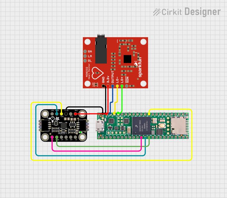
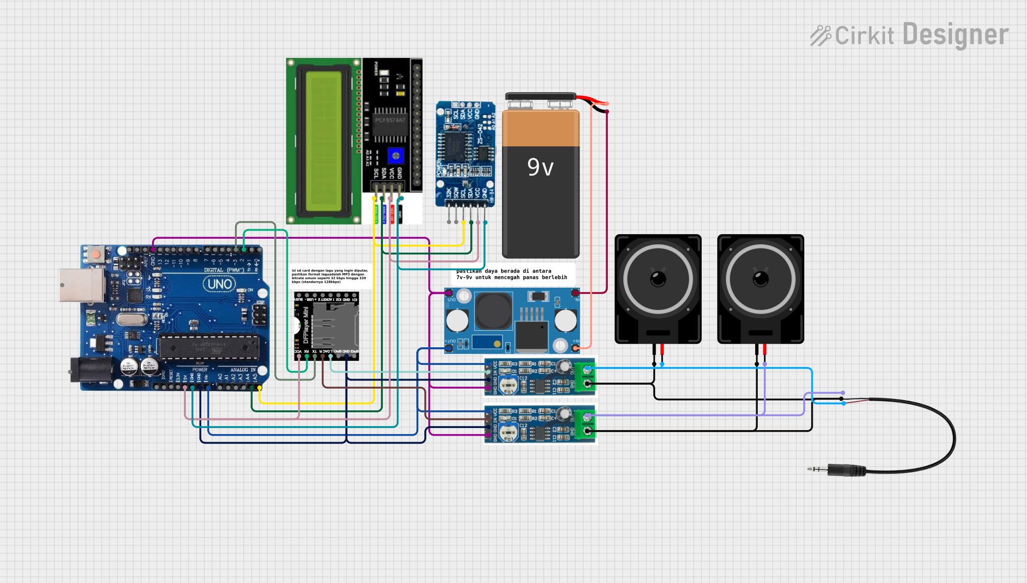

Explore Projects Built with ADC0834
Common Applications
- Sensor interfacing (e.g., temperature, light, or pressure sensors)
- Data acquisition systems
- Embedded systems requiring analog-to-digital conversion
- Industrial automation and control systems
Technical Specifications
The following are the key technical details of the ADC0834:
| Parameter | Value |
|---|---|
| Resolution | 8-bit |
| Number of Channels | 2 (dual-channel input) |
| Input Voltage Range | 0V to VREF (reference voltage) |
| Reference Voltage (VREF) | 2.5V to 5.0V |
| Supply Voltage (VCC) | 4.5V to 5.5V |
| Conversion Time | 32 clock cycles (typical) |
| Serial Interface | SPI-like (3-wire) |
| Power Consumption | 15 mW (typical) |
| Package Type | PDIP, SOIC |
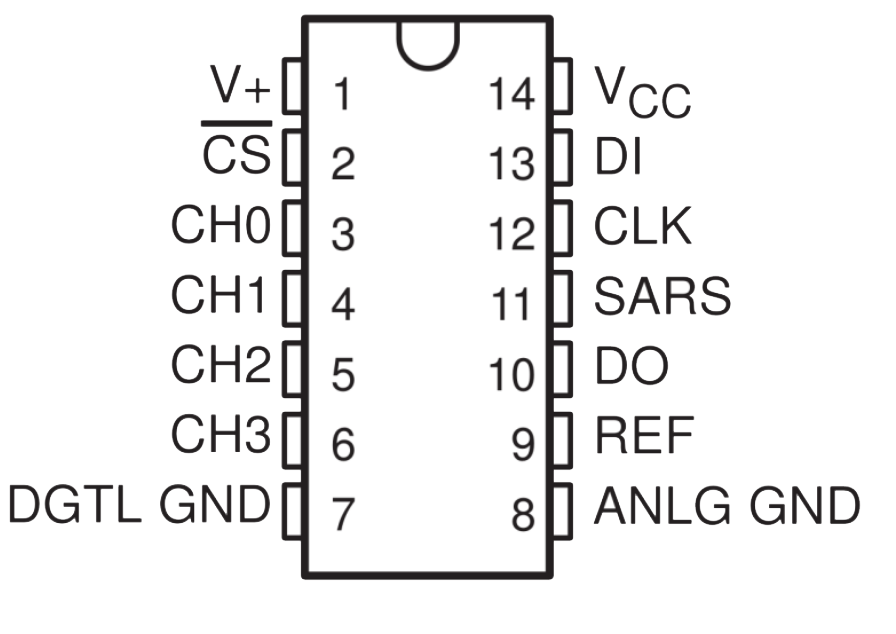
Pin Configuration and Descriptions
The ADC0834 has 8 pins, as described in the table below:
| Pin Number | Pin Name | Description |
|---|---|---|
| 1 | CH0 | Analog input channel 0 |
| 2 | CH1 | Analog input channel 1 |
| 3 | VREF | Reference voltage input (sets input voltage range) |
| 4 | GND | Ground |
| 5 | CS | Chip Select (active low) |
| 6 | CLK | Clock input for serial communication |
| 7 | DOUT | Serial data output |
| 8 | VCC | Power supply (4.5V to 5.5V) |
Usage Instructions
How to Use the ADC0834 in a Circuit
Power Supply and Reference Voltage:
- Connect the VCC pin to a 5V power supply and the GND pin to ground.
- Provide a stable reference voltage (VREF) to set the input voltage range. For example, if VREF is 5V, the input range is 0V to 5V.
Analog Inputs:
- Connect the analog signals to CH0 and/or CH1. Ensure the input voltage does not exceed the reference voltage.
Serial Communication:
- Use the CS, CLK, and DOUT pins for communication with a microcontroller. Pull CS low to enable the ADC0834, and use the CLK pin to synchronize data transfer.
Data Reading:
- The ADC0834 outputs an 8-bit digital value corresponding to the analog input. The value can be read serially via the DOUT pin.
Best Practices
- Use decoupling capacitors (e.g., 0.1 µF) between VCC and GND to reduce noise.
- Ensure the reference voltage is stable and free from fluctuations for accurate conversions.
- Avoid exceeding the input voltage range to prevent damage to the ADC0834.
Example: Connecting ADC0834 to Arduino UNO
Below is an example of how to interface the ADC0834 with an Arduino UNO to read an analog signal:
// Pin definitions for ADC0834
const int CS_PIN = 10;  // Chip Select pin
const int CLK_PIN = 13; // Clock pin
const int DOUT_PIN = 12; // Data Out pin

void setup() {
  pinMode(CS_PIN, OUTPUT);  // Set CS as output
  pinMode(CLK_PIN, OUTPUT); // Set CLK as output
  pinMode(DOUT_PIN, INPUT); // Set DOUT as input

  digitalWrite(CS_PIN, HIGH); // Initialize CS to HIGH (inactive)
  digitalWrite(CLK_PIN, LOW); // Initialize CLK to LOW

  Serial.begin(9600); // Start serial communication
}

int readADC0834(int channel) {
  int result = 0;

  // Start communication
  digitalWrite(CS_PIN, LOW); // Activate ADC0834
  delayMicroseconds(2);

  // Send start bit and channel selection
  for (int i = 0; i < 5; i++) {
    if (i == 0 || i == 1) {
      digitalWrite(CLK_PIN, HIGH); // Send start bit and channel select
      delayMicroseconds(2);
      digitalWrite(CLK_PIN, LOW);
    } else {
      digitalWrite(CLK_PIN, HIGH); // Send remaining bits
      delayMicroseconds(2);
      digitalWrite(CLK_PIN, LOW);
    }
  }

  // Read 8-bit data from ADC0834
  for (int i = 0; i < 8; i++) {
    digitalWrite(CLK_PIN, HIGH);
    delayMicroseconds(2);
    result = (result << 1) | digitalRead(DOUT_PIN); // Shift and read data
    digitalWrite(CLK_PIN, LOW);
  }

  digitalWrite(CS_PIN, HIGH); // Deactivate ADC0834
  return result;
}

void loop() {
  int analogValue = readADC0834(0); // Read from channel 0
  Serial.println(analogValue);     // Print the digital value
  delay(500);                      // Wait for 500ms
}
Notes:
- The
readADC0834function reads an 8-bit digital value from the specified channel. - Ensure the CS, CLK, and DOUT pins are correctly connected to the Arduino.
Troubleshooting and FAQs
Common Issues
No Output or Incorrect Readings:
- Ensure the power supply (VCC) and ground (GND) are properly connected.
- Verify that the reference voltage (VREF) is stable and within the specified range.
Fluctuating or Noisy Data:
- Use decoupling capacitors to filter noise from the power supply.
- Check for proper grounding and minimize interference from nearby components.
Communication Errors:
- Ensure the clock signal (CLK) is stable and within the timing requirements.
- Verify that the CS pin is pulled low during data transfer.
FAQs
Q: Can I use the ADC0834 with a 3.3V microcontroller?
A: The ADC0834 requires a supply voltage (VCC) of 4.5V to 5.5V. However, you can use level shifters to interface it with a 3.3V microcontroller.
Q: What happens if the input voltage exceeds VREF?
A: Exceeding the reference voltage can result in inaccurate readings or damage to the ADC0834. Always ensure the input voltage is within the specified range.
Q: Can I use both channels simultaneously?
A: The ADC0834 can sample one channel at a time. You can alternate between channels by selecting the desired channel during communication.
Q: How do I improve accuracy?
A: Use a stable reference voltage, minimize noise, and ensure proper grounding in your circuit.