Cirkit Designer
Your all-in-one circuit design IDE
Home /
Component Documentation
How to Use WLR089-CanSAT: Examples, Pinouts, and Specs
Introduction
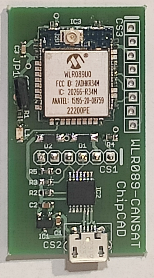
The WLR089-CanSAT is a microcontroller module specifically designed for satellite and IoT applications. It features LoRa communication capabilities, enabling long-range, low-power data transmission. This makes it ideal for use in remote sensing, environmental monitoring, and other applications where reliable, long-distance communication is essential.
Explore Projects Built with WLR089-CanSAT
Satellite Compass and Network-Integrated GPS Data Processing System

This circuit comprises a satellite compass, a mini PC, two GPS antennas, power supplies, a network switch, media converters, and an atomic rubidium clock. The satellite compass is powered by a triple output DC power supply and interfaces with an RS232 splitter for 1PPS signals. The mini PCs are connected to the USRP B200 devices via USB for data and power, and to media converters via Ethernet, which in turn connect to a network switch using fiber optic links. The antennas are connected to the USRP B200s through RF directional couplers, and the atomic clock provides a 1PPS input to the RS232 splitter.
Satellite-Based Timing and Navigation System with SDR and Atomic Clock Synchronization

This circuit appears to be a complex system involving power supply management, GPS and timing synchronization, and data communication. It includes a SI-TEX G1 Satellite Compass for GPS data, an XHTF1021 Atomic Rubidium Clock for precise timing, and Ettus USRP B200 units for software-defined radio communication. Power is supplied through various SMPS units and distributed via terminal blocks and DC jacks. Data communication is facilitated by Beelink MINI S12 N95 computers, RS232 splitters, and a 1000BASE-T Media Converter for network connectivity. RF Directional Couplers are used to interface antennas with the USRP units, and the entire system is likely contained within cases for protection and organization.
Battery-Powered Raspberry Pi Pico GPS Tracker with Sensor Integration

This circuit is a data acquisition and communication system powered by a LiPoly battery and managed by a Raspberry Pi Pico. It includes sensors (BMP280, MPU9250) for environmental data, a GPS module for location tracking, an SD card for data storage, and a WLR089-CanSAT for wireless communication. The TP4056 module handles battery charging, and a toggle switch controls power distribution.
Arduino UNO WiFi CAN Bus Interface with Sensor/Actuator Module
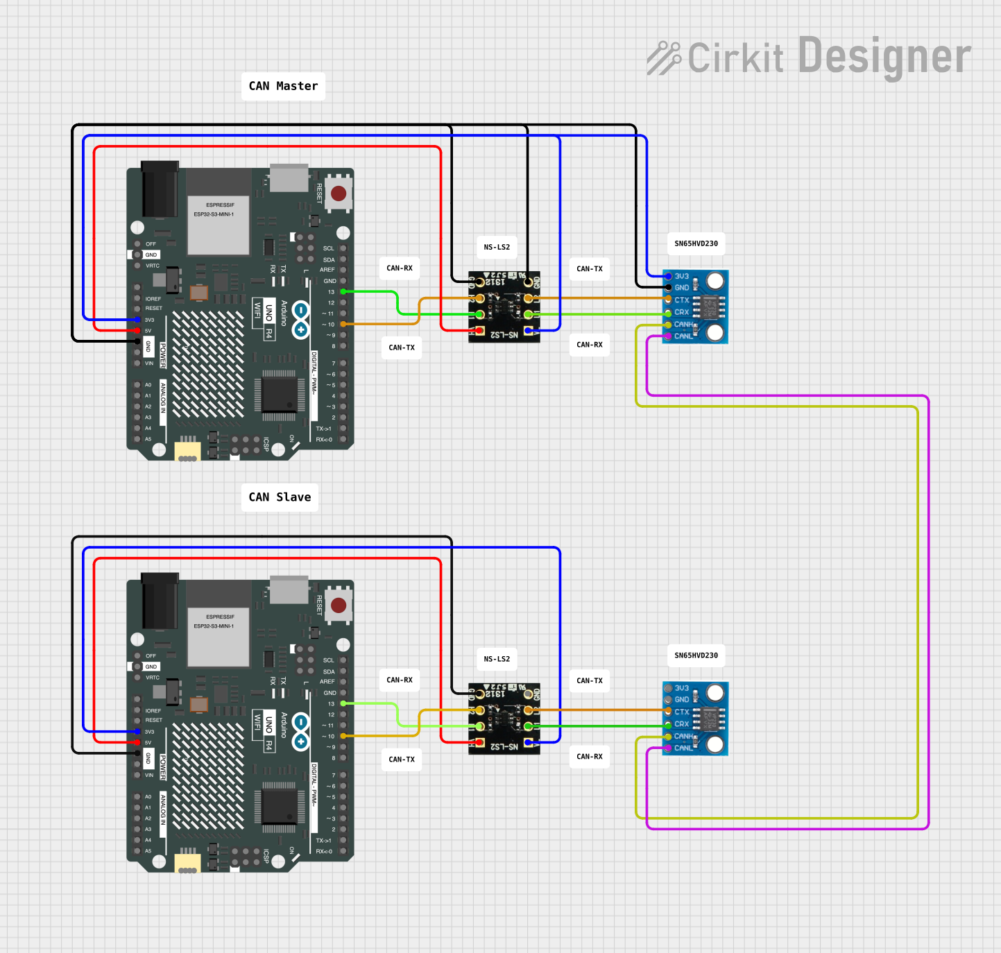
This circuit features two Arduino UNO R4 WiFi microcontrollers interfaced with NS-LS2 light sensors and CAN_SN65HVD230 CAN bus transceivers. The Arduinos are configured to read light intensity data from the NS-LS2 sensors and communicate with each other over a CAN network, likely for a distributed sensing application. Power distribution is managed with 3.3V and 5V connections to the respective components, and the ground connections are shared across the devices to complete the circuit.
Explore Projects Built with WLR089-CanSAT
Satellite Compass and Network-Integrated GPS Data Processing System
This circuit comprises a satellite compass, a mini PC, two GPS antennas, power supplies, a network switch, media converters, and an atomic rubidium clock. The satellite compass is powered by a triple output DC power supply and interfaces with an RS232 splitter for 1PPS signals. The mini PCs are connected to the USRP B200 devices via USB for data and power, and to media converters via Ethernet, which in turn connect to a network switch using fiber optic links. The antennas are connected to the USRP B200s through RF directional couplers, and the atomic clock provides a 1PPS input to the RS232 splitter.
Satellite-Based Timing and Navigation System with SDR and Atomic Clock Synchronization
This circuit appears to be a complex system involving power supply management, GPS and timing synchronization, and data communication. It includes a SI-TEX G1 Satellite Compass for GPS data, an XHTF1021 Atomic Rubidium Clock for precise timing, and Ettus USRP B200 units for software-defined radio communication. Power is supplied through various SMPS units and distributed via terminal blocks and DC jacks. Data communication is facilitated by Beelink MINI S12 N95 computers, RS232 splitters, and a 1000BASE-T Media Converter for network connectivity. RF Directional Couplers are used to interface antennas with the USRP units, and the entire system is likely contained within cases for protection and organization.
Battery-Powered Raspberry Pi Pico GPS Tracker with Sensor Integration
This circuit is a data acquisition and communication system powered by a LiPoly battery and managed by a Raspberry Pi Pico. It includes sensors (BMP280, MPU9250) for environmental data, a GPS module for location tracking, an SD card for data storage, and a WLR089-CanSAT for wireless communication. The TP4056 module handles battery charging, and a toggle switch controls power distribution.
Arduino UNO WiFi CAN Bus Interface with Sensor/Actuator Module
This circuit features two Arduino UNO R4 WiFi microcontrollers interfaced with NS-LS2 light sensors and CAN_SN65HVD230 CAN bus transceivers. The Arduinos are configured to read light intensity data from the NS-LS2 sensors and communicate with each other over a CAN network, likely for a distributed sensing application. Power distribution is managed with 3.3V and 5V connections to the respective components, and the ground connections are shared across the devices to complete the circuit.
Common Applications and Use Cases
- Satellite Communication: Ideal for small satellite projects, including CubeSats and CanSats.
- IoT Networks: Suitable for creating low-power, long-range IoT networks.
- Remote Sensing: Useful in environmental monitoring, agriculture, and other remote sensing applications.
- Telemetry: Perfect for telemetry applications in various fields such as weather stations and wildlife tracking.
Technical Specifications
Key Technical Details
| Parameter | Value |
|---|---|
| Microcontroller | ARM Cortex-M0+ |
| Operating Voltage | 1.8V - 3.6V |
| Communication | LoRa, UART, SPI, I2C |
| Flash Memory | 256 KB |
| SRAM | 40 KB |
| Frequency Range | 868 MHz (EU) / 915 MHz (US) |
| Power Consumption | 1.2 µA (Sleep), 15 mA (TX) |
| Operating Temperature | -40°C to +85°C |
Pin Configuration and Descriptions
| Pin Number | Pin Name | Description |
|---|---|---|
| 1 | VCC | Power Supply (1.8V - 3.6V) |
| 2 | GND | Ground |
| 3 | TX | UART Transmit |
| 4 | RX | UART Receive |
| 5 | SCK | SPI Clock |
| 6 | MISO | SPI Master In Slave Out |
| 7 | MOSI | SPI Master Out Slave In |
| 8 | CS | SPI Chip Select |
| 9 | SDA | I2C Data |
| 10 | SCL | I2C Clock |
| 11 | ANT | Antenna Connection |
| 12 | RST | Reset |
Usage Instructions
How to Use the Component in a Circuit
- Power Supply: Connect the VCC pin to a power supply within the range of 1.8V to 3.6V. Connect the GND pin to the ground of your circuit.
- Communication Interface: Depending on your application, connect the appropriate communication pins (UART, SPI, or I2C) to your microcontroller or other devices.
- Antenna: Connect an appropriate antenna to the ANT pin for LoRa communication.
- Reset: Optionally, connect a push-button or a microcontroller GPIO pin to the RST pin to reset the module.
Important Considerations and Best Practices
- Power Supply: Ensure that the power supply is stable and within the specified range to avoid damaging the module.
- Antenna: Use a suitable antenna for the frequency range you are operating in (868 MHz for EU, 915 MHz for US) to ensure optimal performance.
- Communication Protocols: Choose the communication protocol (UART, SPI, I2C) that best fits your application requirements.
- Environmental Conditions: Operate the module within the specified temperature range (-40°C to +85°C) to ensure reliable performance.
Example: Connecting to an Arduino UNO
Wiring Diagram
| WLR089-CanSAT Pin | Arduino UNO Pin |
|---|---|
| VCC | 3.3V |
| GND | GND |
| TX | RX (Pin 0) |
| RX | TX (Pin 1) |
| ANT | Antenna |
| RST | Digital Pin 7 |
Sample Code
#include <SoftwareSerial.h>

SoftwareSerial mySerial(0, 1); // RX, TX

void setup() {
  // Initialize serial communication at 9600 baud rate
  Serial.begin(9600);
  mySerial.begin(9600);

  // Reset the WLR089-CanSAT module
  pinMode(7, OUTPUT);
  digitalWrite(7, LOW);
  delay(100);
  digitalWrite(7, HIGH);
}

void loop() {
  // Check if data is available from the WLR089-CanSAT module
  if (mySerial.available()) {
    // Read the data and print it to the Serial Monitor
    Serial.write(mySerial.read());
  }

  // Check if data is available from the Serial Monitor
  if (Serial.available()) {
    // Read the data and send it to the WLR089-CanSAT module
    mySerial.write(Serial.read());
  }
}
Troubleshooting and FAQs
Common Issues Users Might Face
No Communication:
- Solution: Ensure that the communication pins (TX, RX) are correctly connected and that the baud rate is correctly set in the code.
Module Not Powering On:
- Solution: Check the power supply connections and ensure that the voltage is within the specified range (1.8V - 3.6V).
Poor Signal Quality:
- Solution: Verify that the antenna is properly connected and is suitable for the operating frequency. Ensure there are no obstructions or sources of interference nearby.
Module Not Responding:
- Solution: Try resetting the module by toggling the RST pin. Ensure that the module is not in sleep mode.
Solutions and Tips for Troubleshooting
- Check Connections: Double-check all connections to ensure they are secure and correctly placed.
- Use a Multimeter: Measure the voltage at the VCC pin to ensure the module is receiving the correct power supply.
- Serial Monitor: Use the Serial Monitor in the Arduino IDE to debug communication issues by printing out received data.
- Consult Datasheet: Refer to the WLR089-CanSAT datasheet for detailed technical information and troubleshooting tips.
By following this documentation, users should be able to effectively integrate the WLR089-CanSAT module into their projects, ensuring reliable and efficient long-range communication for their satellite and IoT applications.