How to Use fm radio reciver: Examples, Pinouts, and Specs
Introduction
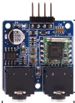
The FM Radio Receiver is a device designed to receive frequency-modulated (FM) radio signals and convert them into audio signals for playback. It enables users to tune into FM radio broadcasts, providing access to music, news, and other audio content transmitted over FM frequencies. FM radio receivers are widely used in consumer electronics, such as portable radios, car stereos, and home audio systems.
Explore Projects Built with fm radio reciver

Explore Projects Built with fm radio reciver
Common Applications and Use Cases
- Portable FM radios for personal use
- Car audio systems for in-vehicle entertainment
- Home stereo systems for FM broadcast reception
- DIY electronics projects involving audio playback
- Integration into microcontroller-based systems for custom FM radio functionality
Technical Specifications
Below are the general technical specifications for a typical FM radio receiver module, such as the TEA5767 or similar:
| Parameter | Value |
|---|---|
| Operating Voltage | 2.7V to 5.5V |
| Operating Current | ~10mA to 20mA |
| Frequency Range | 76 MHz to 108 MHz |
| Audio Output | Stereo or Mono (depending on module) |
| Interface | I2C or Analog Tuning |
| Sensitivity | ~2 µV for 26 dB S/N ratio |
| Antenna Input | External antenna required |
| Output Impedance | ~32Ω (for headphone output) |
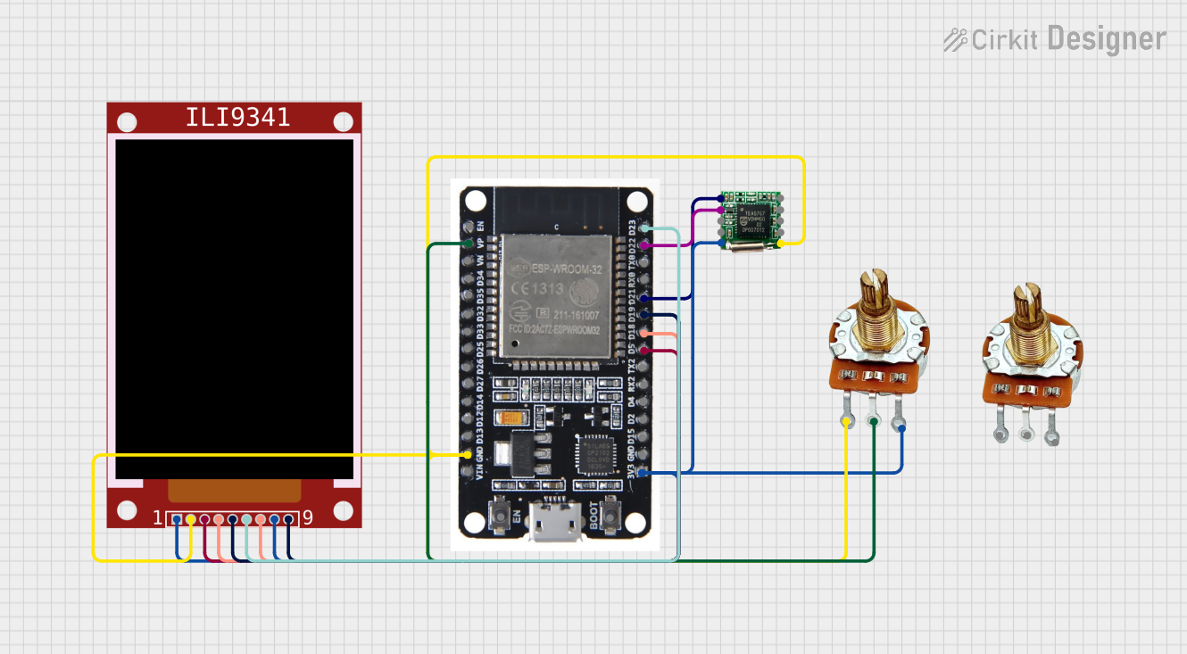
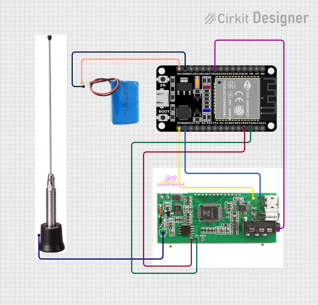
Pin Configuration and Descriptions
The pinout for an FM radio receiver module (e.g., TEA5767) is as follows:
| Pin Name | Description |
|---|---|
| VCC | Power supply input (2.7V to 5.5V) |
| GND | Ground connection |
| SDA | I2C data line for communication |
| SCL | I2C clock line for communication |
| ANT | Antenna input for receiving FM signals |
| LOUT | Left audio output |
| ROUT | Right audio output |
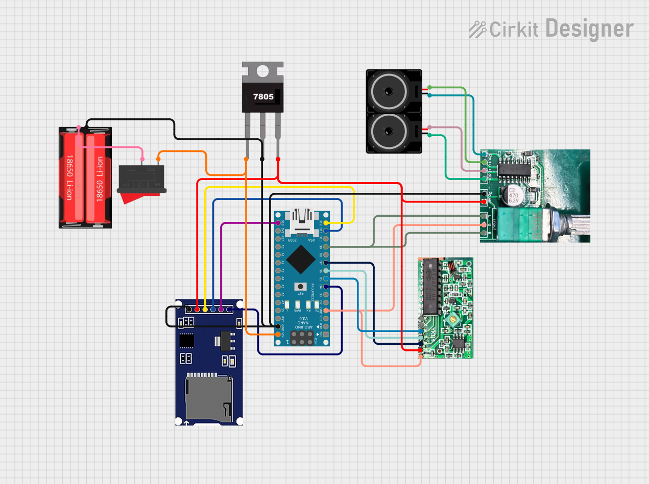
Usage Instructions
How to Use the Component in a Circuit
- Power Supply: Connect the VCC pin to a 3.3V or 5V power source and the GND pin to the ground.
- Antenna: Attach an external antenna to the ANT pin to improve signal reception. A simple wire can often suffice.
- Audio Output: Connect the LOUT and ROUT pins to a stereo amplifier or headphones for audio playback.
- Microcontroller Interface: Use the SDA and SCL pins to communicate with the module via the I2C protocol. This allows you to control the frequency tuning and other settings programmatically.
Important Considerations and Best Practices
- Antenna Placement: Ensure the antenna is positioned away from sources of interference, such as power supplies or other electronic components.
- Power Supply Noise: Use a decoupling capacitor (e.g., 0.1 µF) near the VCC pin to reduce noise and improve performance.
- Audio Amplification: If the audio output is too low, use an external amplifier to boost the signal for speakers or headphones.
- I2C Pull-Up Resistors: Add pull-up resistors (e.g., 4.7 kΩ) to the SDA and SCL lines if they are not already present in your circuit.
Example Code for Arduino UNO
Below is an example of how to use an FM radio receiver module (e.g., TEA5767) with an Arduino UNO:
#include <Wire.h> // Include the Wire library for I2C communication

#define TEA5767_I2C_ADDRESS 0x60 // I2C address of the TEA5767 module

void setup() {
  Wire.begin(); // Initialize I2C communication
  Serial.begin(9600); // Start serial communication for debugging
  setFrequency(101.1); // Set the FM frequency to 101.1 MHz
}

void loop() {
  // The main loop can be used to adjust frequency or handle other tasks
}

// Function to set the FM frequency
void setFrequency(float frequency) {
  uint16_t frequencyB = (frequency * 1000000 + 225000) / 32768;
  // Convert frequency to binary format for TEA5767
  byte data[5];
  data[0] = frequencyB >> 8; // High byte of frequency
  data[1] = frequencyB & 0xFF; // Low byte of frequency
  data[2] = 0xB0; // Set stereo and high side injection
  data[3] = 0x10; // Mute off
  data[4] = 0x00; // Reserved byte

  Wire.beginTransmission(TEA5767_I2C_ADDRESS); // Start I2C transmission
  Wire.write(data, 5); // Send frequency data
  Wire.endTransmission(); // End I2C transmission
  delay(100); // Allow time for the module to tune
}
Notes:
- Replace
101.1in thesetFrequencyfunction with your desired FM frequency. - Ensure the antenna is connected for optimal signal reception.
Troubleshooting and FAQs
Common Issues and Solutions
No Audio Output:
- Ensure the audio output pins (LOUT and ROUT) are properly connected to an amplifier or headphones.
- Verify that the module is powered correctly and the antenna is connected.
Poor Signal Reception:
- Check the antenna placement and ensure it is not obstructed or too close to other electronic components.
- Use a longer or higher-quality antenna for better reception.
I2C Communication Failure:
- Verify the SDA and SCL connections between the module and the microcontroller.
- Check for proper pull-up resistors on the I2C lines.
Distorted Audio:
- Ensure the power supply is stable and free of noise.
- Use an external amplifier if the audio output is too weak.
FAQs
Q: Can I use this module with a 5V microcontroller?
A: Yes, most FM radio receiver modules are compatible with 5V systems. However, check the specific module's datasheet to confirm.
Q: What type of antenna should I use?
A: A simple wire antenna (e.g., 75 cm long) works well for most applications. For better performance, use a telescopic or dipole antenna.
Q: How do I change the frequency programmatically?
A: Use the setFrequency function in the provided Arduino code, passing the desired frequency as a parameter.
Q: Can this module output stereo audio?
A: Yes, most FM radio receiver modules support stereo audio output, provided the broadcast signal is in stereo.
By following this documentation, you can successfully integrate and use an FM radio receiver module in your projects.