
How to Use Photon: Examples, Pinouts, and Specs
 Design with Photon in Cirkit Designer
Introduction
The Photon, developed by Particle, is a powerful Wi-Fi-enabled microcontroller designed for IoT (Internet of Things) applications. It combines the flexibility of a microcontroller with the connectivity of Wi-Fi, making it an ideal choice for building connected devices. The Photon is based on the Broadcom BCM43362 Wi-Fi chip and features a powerful ARM Cortex-M3 microcontroller.
Common applications and use cases for the Photon include:
- Smart home devices
- Industrial IoT systems
- Prototyping connected products
- Remote monitoring and control
- Educational projects and learning IoT development
Explore Projects Built with Photon
 Open Project in Cirkit Designer
 Open Project in Cirkit Designer
 Open Project in Cirkit Designer
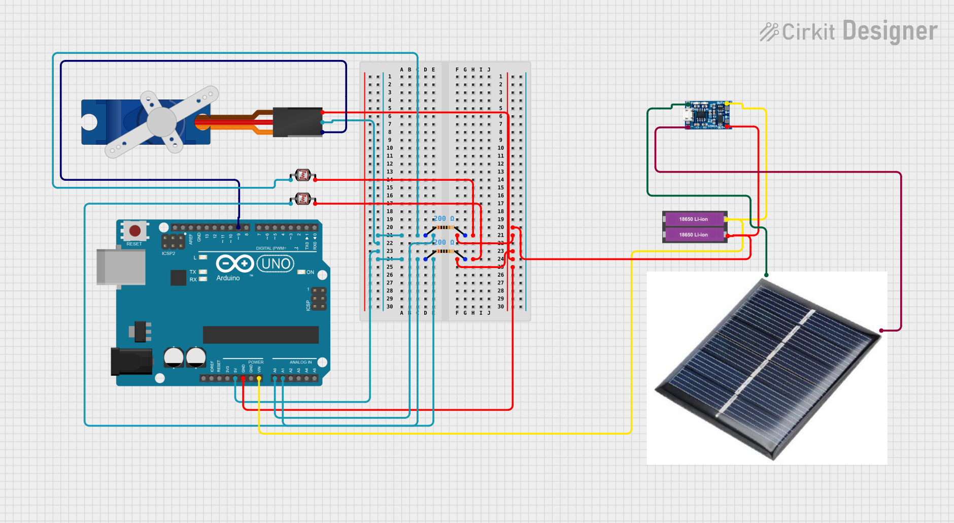 Open Project in Cirkit Designer
Explore Projects Built with Photon
Open Project in Cirkit DesignerOpen Project in Cirkit DesignerOpen Project in Cirkit DesignerOpen Project in Cirkit DesignerTechnical Specifications
The Photon is packed with features that make it versatile and easy to use in a wide range of applications. Below are its key technical details:
General Specifications
| Feature | Specification |
|---|---|
| Microcontroller | STM32F205 ARM Cortex-M3 (120 MHz) |
| Wi-Fi Module | Broadcom BCM43362 |
| Flash Memory | 1 MB |
| RAM | 128 KB |
| Operating Voltage | 3.3V |
| Input Voltage (VIN) | 3.6V to 5.5V |
| Digital I/O Pins | 18 |
| Analog Input Pins | 8 (12-bit ADC) |
| PWM Pins | 9 |
| Communication Interfaces | UART, SPI, I2C |
| Dimensions | 36.58 mm x 20.32 mm |
Pin Configuration and Descriptions
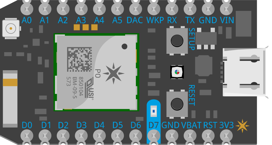
The Photon has a total of 24 pins, including power, ground, and I/O pins. Below is the pinout description:
| Pin Name | Type | Description |
|---|---|---|
| VIN | Power Input | Input voltage pin (3.6V to 5.5V). Used to power the Photon. |
| 3V3 | Power Output | Regulated 3.3V output. Can supply up to 100 mA to external components. |
| GND | Ground | Ground pin. Connect to the ground of your circuit. |
| D0-D7 | Digital I/O | General-purpose digital pins. Can be used for input or output. |
| A0-A7 | Analog Input | Analog input pins (12-bit resolution). Can also be used as digital I/O. |
| TX | UART TX | Transmit pin for UART communication. |
| RX | UART RX | Receive pin for UART communication. |
| WKP | Wake Pin | Used to wake the Photon from deep sleep mode. |
| RST | Reset | Resets the Photon when pulled low. |
| DAC | Analog Output | Digital-to-Analog Converter output pin. |
| VBAT | Battery Input | Connect to a backup battery for RTC (Real-Time Clock) functionality. |
Usage Instructions
The Photon is designed to be easy to use, even for beginners. Below are the steps and best practices for using the Photon in a circuit:
Setting Up the Photon
- Powering the Photon: Connect the VIN pin to a 5V power source or use a USB cable to power the device.
- Connecting to Wi-Fi: Use the Particle mobile app or Particle CLI to configure the Photon to connect to your Wi-Fi network.
- Programming the Photon: Write and upload code to the Photon using the Particle Web IDE, Particle CLI, or a local development environment.
Example: Blinking an LED
The following example demonstrates how to blink an LED connected to pin D7 of the Photon:
// This code blinks an LED connected to pin D7 on the Photon.
// D7 is the onboard LED pin, so no external LED is required.

void setup() {
  pinMode(D7, OUTPUT); // Set D7 as an output pin
}

void loop() {
  digitalWrite(D7, HIGH); // Turn the LED on
  delay(1000);            // Wait for 1 second
  digitalWrite(D7, LOW);  // Turn the LED off
  delay(1000);            // Wait for 1 second
}
Important Considerations
- Voltage Levels: Ensure that all connected components operate at 3.3V logic levels to avoid damaging the Photon.
- Wi-Fi Signal Strength: Place the Photon in an area with a strong Wi-Fi signal for reliable connectivity.
- Power Supply: Use a stable power source to prevent unexpected resets or malfunctions.
Troubleshooting and FAQs
Common Issues
Photon Not Connecting to Wi-Fi
- Cause: Incorrect Wi-Fi credentials or weak signal.
- Solution: Double-check the Wi-Fi SSID and password. Ensure the Photon is within range of the router.
Code Not Uploading
- Cause: USB driver issues or incorrect device selection in the IDE.
- Solution: Reinstall the Particle USB drivers and ensure the correct device is selected in the IDE.
Photon Not Powering On
- Cause: Insufficient power supply or damaged hardware.
- Solution: Verify the power source and check for physical damage to the Photon.
FAQs
Q: Can the Photon be powered by a battery?
A: Yes, the Photon can be powered using a LiPo battery connected to the VIN pin. Ensure the battery voltage is within the 3.6V to 5.5V range.
Q: How do I reset the Photon to factory settings?
A: Hold down the SETUP button, then press and release the RESET button. Continue holding SETUP until the status LED blinks white, indicating a factory reset.
Q: Can I use the Photon with Arduino libraries?
A: Many Arduino libraries are compatible with the Photon. You may need to make minor modifications to ensure compatibility.
By following this documentation, you can effectively use the Particle Photon in your IoT projects and troubleshoot common issues with ease.