How to Use sct 013: Examples, Pinouts, and Specs
Introduction
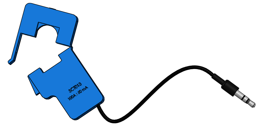
The SCT-013 is a non-invasive current transformer (CT) sensor designed for measuring alternating current (AC). Manufactured by Arduino, this sensor allows for the measurement of current flowing through a conductor without the need for direct electrical contact. This makes it an ideal component for energy monitoring systems, where safety and ease of installation are paramount.
Explore Projects Built with sct 013

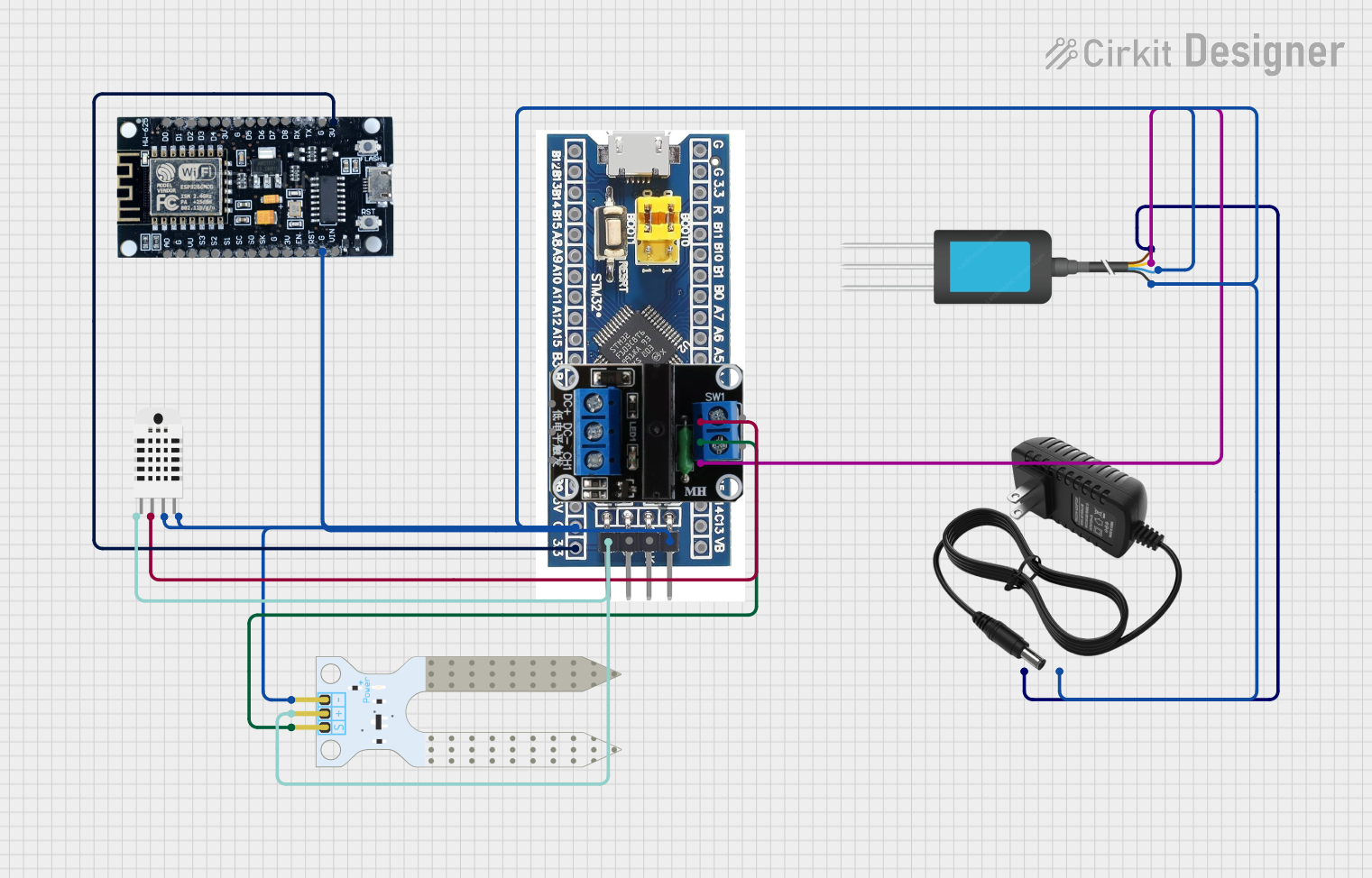


Explore Projects Built with sct 013
Common Applications and Use Cases
- Energy Monitoring Systems: Used to measure the current consumption of electrical appliances and systems.
- Smart Home Automation: Integrated into smart home systems to monitor and manage energy usage.
- Industrial Automation: Employed in industrial settings to monitor machinery and equipment for maintenance and efficiency.
- Renewable Energy Systems: Used in solar and wind energy systems to monitor the output and efficiency of the installations.
Technical Specifications
Key Technical Details
| Parameter | Value |
|---|---|
| Manufacturer | Arduino |
| Part ID | UNO |
| Model | SCT-013 |
| Measurement Range | 0-100A AC |
| Output Signal | 0-1V AC |
| Accuracy | ±1% |
| Operating Temperature | -25°C to 70°C |
| Cable Length | 1 meter |
| Core Material | Ferrite |
| Housing Material | ABS Plastic |
Pin Configuration and Descriptions
| Pin Number | Pin Name | Description |
|---|---|---|
| 1 | VCC | Power supply (typically 5V from Arduino) |
| 2 | GND | Ground |
| 3 | Signal | Analog output signal proportional to measured AC |
Usage Instructions
How to Use the SCT-013 in a Circuit
Connect the SCT-013 to the Conductor:
- Open the clamp of the SCT-013 and place it around the conductor whose current you wish to measure. Ensure the clamp is securely closed.
Connect to Arduino UNO:
- Connect the VCC pin of the SCT-013 to the 5V pin on the Arduino UNO.
- Connect the GND pin of the SCT-013 to the GND pin on the Arduino UNO.
- Connect the Signal pin of the SCT-013 to an analog input pin (e.g., A0) on the Arduino UNO.
Load the Code:
- Upload the following code to your Arduino UNO to read the current values from the SCT-013.
// SCT-013 Current Sensor Example Code
// This code reads the analog signal from the SCT-013 sensor and converts it
// to a current value.

const int sensorPin = A0; // Analog input pin for SCT-013
float calibrationFactor = 100.0; // Calibration factor for SCT-013

void setup() {
  Serial.begin(9600); // Initialize serial communication
}

void loop() {
  int sensorValue = analogRead(sensorPin); // Read the analog input
  float voltage = sensorValue * (5.0 / 1023.0); // Convert to voltage
  float current = voltage * calibrationFactor; // Convert to current

  Serial.print("Current: ");
  Serial.print(current);
  Serial.println(" A");

  delay(1000); // Wait for 1 second before next reading
}
Important Considerations and Best Practices
- Calibration: The calibration factor may need to be adjusted based on the specific SCT-013 model and the range of current being measured. Refer to the datasheet for precise calibration instructions.
- Safety: Ensure the SCT-013 is securely clamped around the conductor and that the conductor is insulated. Avoid placing the sensor around live wires without proper insulation.
- Noise Reduction: To reduce noise in the signal, consider using a low-pass filter or averaging multiple readings in your code.
Troubleshooting and FAQs
Common Issues and Solutions
No Signal Output:
- Solution: Ensure the SCT-013 is properly clamped around the conductor and that the connections to the Arduino are secure.
Inaccurate Readings:
- Solution: Check the calibration factor in the code. Adjust it based on the specific model and range of current being measured.
Fluctuating Readings:
- Solution: Implement a low-pass filter in the code or average multiple readings to reduce noise.
FAQs
Q: Can the SCT-013 measure DC current? A: No, the SCT-013 is designed to measure AC current only.
Q: What is the maximum current the SCT-013 can measure? A: The SCT-013 can measure up to 100A AC.
Q: How do I calibrate the SCT-013? A: Calibration involves adjusting the calibration factor in the code based on known current values. Refer to the datasheet for detailed calibration instructions.
Q: Can I use the SCT-013 with other microcontrollers? A: Yes, the SCT-013 can be used with other microcontrollers that have analog input pins, such as the ESP8266, ESP32, and others.
By following this documentation, users can effectively integrate the SCT-013 non-invasive current transformer sensor into their projects, ensuring accurate and reliable current measurements.