How to Use WEMOS D1 R1: Examples, Pinouts, and Specs

Introduction
The WEMOS D1 R1 is a microcontroller board based on the ESP8266 Wi-Fi module, designed specifically for Internet of Things (IoT) applications. It combines the power of the ESP8266 with the ease of use of an Arduino-like form factor, making it an excellent choice for both beginners and experienced developers. The board features a USB interface for programming, multiple GPIO pins for connecting sensors and actuators, and built-in Wi-Fi capabilities for seamless wireless communication.
Explore Projects Built with WEMOS D1 R1

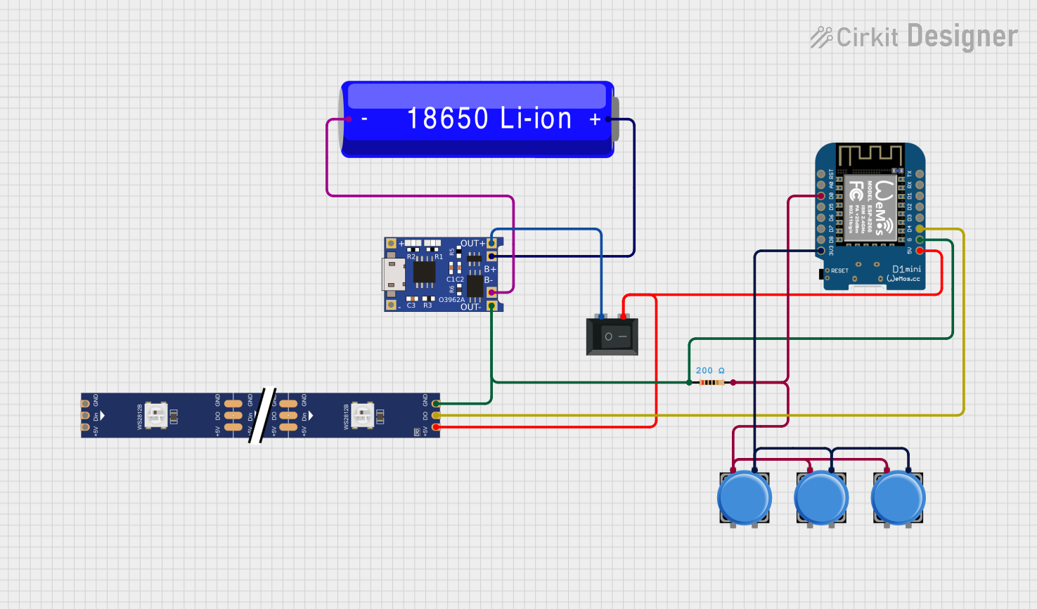
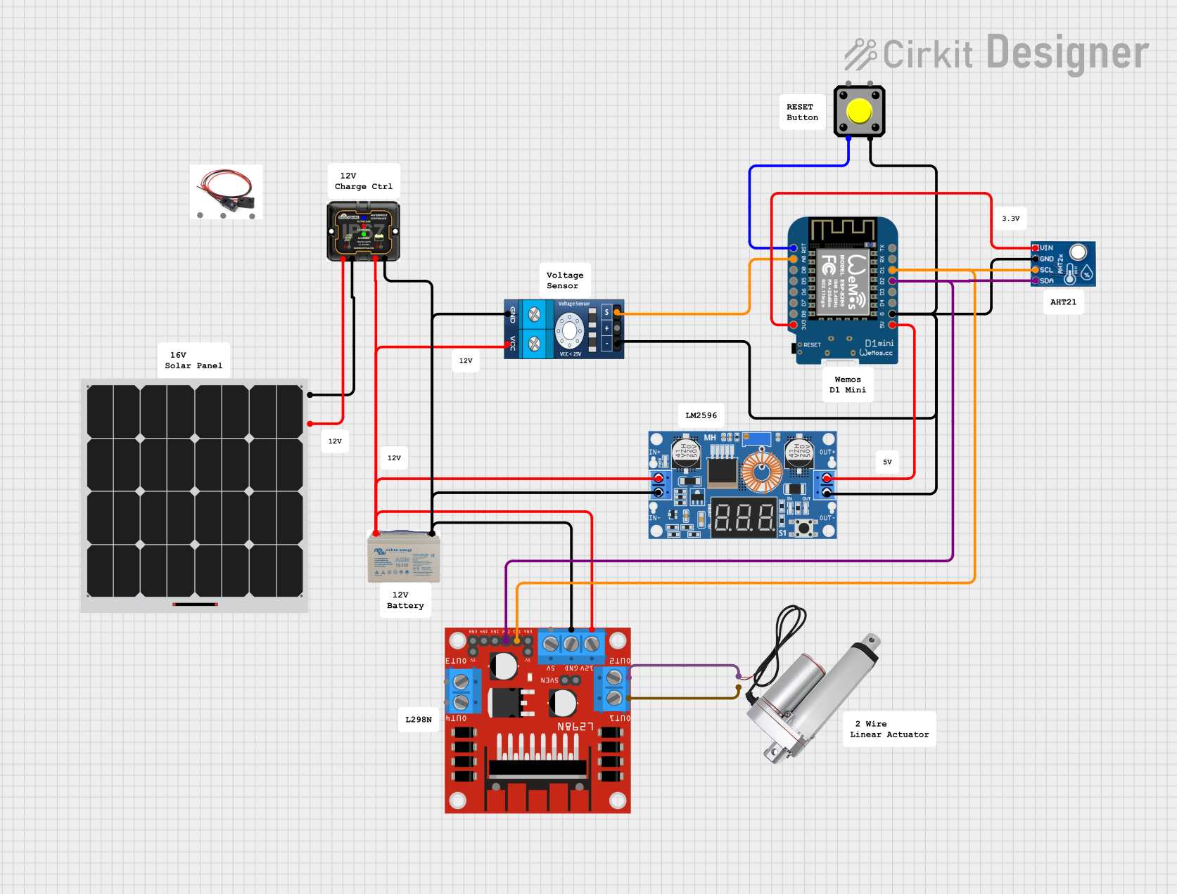

Explore Projects Built with WEMOS D1 R1
Common Applications and Use Cases
- Home automation systems
- Wireless sensor networks
- IoT-enabled devices
- Remote monitoring and control
- Prototyping smart devices
Technical Specifications
Key Technical Details
- Microcontroller: ESP8266EX
- Operating Voltage: 3.3V
- Input Voltage: 7-12V (via barrel jack) or 5V (via USB)
- Digital I/O Pins: 11 (D0-D10)
- Analog Input Pins: 1 (A0, 10-bit resolution)
- Wi-Fi Standard: 802.11 b/g/n
- Flash Memory: 4MB
- Clock Speed: 80 MHz (can be overclocked to 160 MHz)
- USB Interface: Micro-USB
- Dimensions: 68.6mm x 53.4mm
Pin Configuration and Descriptions
The WEMOS D1 R1 has a pinout similar to the Arduino UNO, but with some differences due to the ESP8266 architecture. Below is the pin configuration:
| Pin | Label | Description |
|---|---|---|
| 1 | D0 | GPIO16, can be used as a digital I/O pin |
| 2 | D1 | GPIO5, supports I2C (SCL) |
| 3 | D2 | GPIO4, supports I2C (SDA) |
| 4 | D3 | GPIO0, can be used as a digital I/O pin |
| 5 | D4 | GPIO2, can be used as a digital I/O pin |
| 6 | D5 | GPIO14, supports SPI (SCLK) |
| 7 | D6 | GPIO12, supports SPI (MISO) |
| 8 | D7 | GPIO13, supports SPI (MOSI) |
| 9 | D8 | GPIO15, supports SPI (SS) |
| 10 | A0 | Analog input, 0-3.3V, 10-bit resolution |
| 11 | G | Ground pin |
| 12 | 3V3 | 3.3V output for powering external components |
| 13 | 5V | 5V output (only available when powered via USB or barrel jack) |
| 14 | RST | Reset pin, used to restart the microcontroller |
Usage Instructions
How to Use the WEMOS D1 R1 in a Circuit
Powering the Board:
- Use a Micro-USB cable to power the board and upload code.
- Alternatively, supply 7-12V via the barrel jack or 5V directly to the 5V pin.
Programming the Board:
- Install the Arduino IDE and add the ESP8266 board package via the Board Manager.
- Select "WEMOS D1 R1" as the board type in the Tools menu.
- Connect the board to your computer via USB and upload your code.
Connecting Sensors and Actuators:
- Use the GPIO pins (D0-D8) for digital input/output.
- Use the A0 pin for analog input (ensure the input voltage does not exceed 3.3V).
- For I2C devices, connect to D1 (SCL) and D2 (SDA).
- For SPI devices, use D5 (SCLK), D6 (MISO), D7 (MOSI), and D8 (SS).
Wi-Fi Configuration:
- Use the ESP8266WiFi library to connect the board to a Wi-Fi network.
- The board can act as a client or an access point (AP).
Example Code: Connecting to Wi-Fi
Below is an example sketch to connect the WEMOS D1 R1 to a Wi-Fi network:
#include <ESP8266WiFi.h> // Include the Wi-Fi library

const char* ssid = "Your_SSID";       // Replace with your Wi-Fi network name
const char* password = "Your_Password"; // Replace with your Wi-Fi password

void setup() {
  Serial.begin(115200); // Start the serial communication at 115200 baud
  delay(10);

  Serial.println("Connecting to Wi-Fi...");
  WiFi.begin(ssid, password); // Start connecting to the Wi-Fi network

  while (WiFi.status() != WL_CONNECTED) {
    delay(500); // Wait for the connection to establish
    Serial.print(".");
  }

  Serial.println("\nWi-Fi connected!");
  Serial.print("IP Address: ");
  Serial.println(WiFi.localIP()); // Print the assigned IP address
}

void loop() {
  // Add your main code here
}
Important Considerations and Best Practices
- Voltage Levels: The GPIO pins operate at 3.3V. Avoid applying 5V directly to the pins to prevent damage.
- Power Supply: If using the barrel jack, ensure the input voltage is within the 7-12V range.
- Wi-Fi Signal Strength: Place the board in an area with a strong Wi-Fi signal for reliable communication.
- Heat Management: The ESP8266 can get warm during operation. Ensure proper ventilation if used in an enclosure.
Troubleshooting and FAQs
Common Issues and Solutions
Problem: The board is not detected by the Arduino IDE.
Solution:- Ensure the correct USB driver is installed (e.g., CH340 driver for some versions of the WEMOS D1 R1).
- Check that the correct board and port are selected in the Tools menu.
Problem: The board fails to connect to Wi-Fi.
Solution:- Double-check the SSID and password in your code.
- Ensure the Wi-Fi network is within range and not using unsupported security protocols.
Problem: GPIO pins are not functioning as expected.
Solution:- Verify that the pins are not being used for multiple purposes (e.g., GPIO15 is also used for SPI SS).
- Check for proper wiring and connections.
Problem: The board resets unexpectedly.
Solution:- Ensure the power supply is stable and capable of providing sufficient current (at least 500mA).
- Avoid using long or thin wires for power connections.
FAQs
Can I use the WEMOS D1 R1 with 5V sensors?
Yes, but you will need a level shifter or voltage divider to step down the 5V signal to 3.3V.What is the maximum range of the Wi-Fi module?
The range depends on the environment but is typically around 30-50 meters indoors and up to 100 meters outdoors.Can the WEMOS D1 R1 be powered by batteries?
Yes, you can use a 7-12V battery connected to the barrel jack or a 3.7V LiPo battery with a step-up converter to 5V.Is the WEMOS D1 R1 compatible with Arduino libraries?
Yes, most Arduino libraries are compatible, but some may require modifications for the ESP8266 architecture.