How to Use Notecarrier XM: Examples, Pinouts, and Specs
Introduction
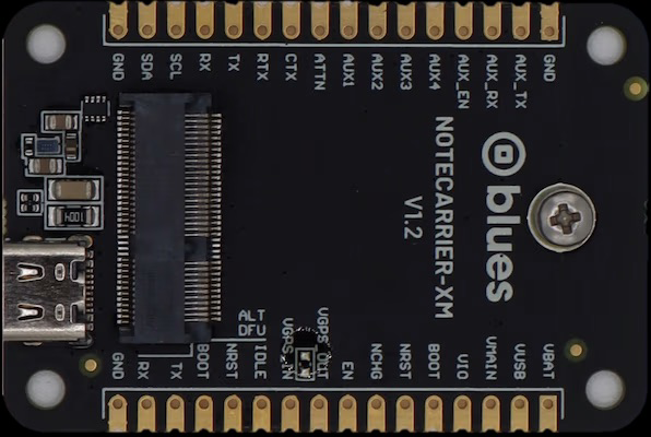
The Notecarrier XM, manufactured by Blues, is a versatile electronic component designed for data storage and transmission. It is commonly used in communication systems to facilitate the transfer of notes and messages in a digital format. This component is particularly valued for its reliability, compact design, and ease of integration into IoT (Internet of Things) applications.
Explore Projects Built with Notecarrier XM
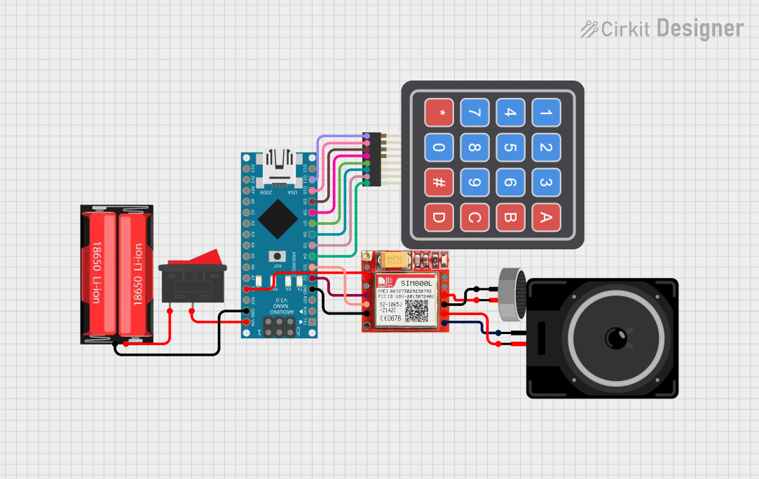


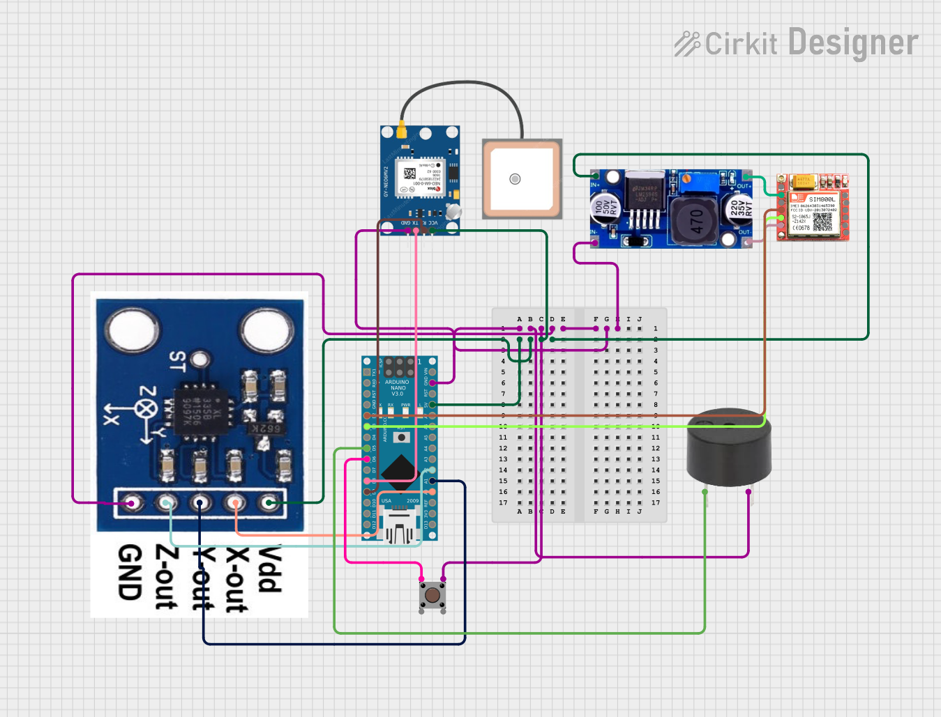
Explore Projects Built with Notecarrier XM
Common Applications and Use Cases
- IoT devices requiring secure and efficient data transmission
- Remote monitoring and control systems
- Data logging and storage in industrial applications
- Communication modules in smart home devices
- Prototyping and development of wireless communication systems
Technical Specifications
The Notecarrier XM is designed to work seamlessly with Blues' Notecard modules, providing a robust platform for data communication. Below are the key technical details and pin configurations:
Key Technical Details
| Parameter | Specification |
|---|---|
| Operating Voltage | 3.3V to 5.5V |
| Communication Interface | I²C, UART |
| Dimensions | 65mm x 30mm x 6mm |
| Operating Temperature | -40°C to +85°C |
| Compatible Modules | Blues Notecard |
| Mounting Type | Surface-mount or breadboard-compatible |
Pin Configuration and Descriptions
| Pin Name | Pin Number | Description |
|---|---|---|
| GND | 1 | Ground connection |
| VIN | 2 | Power input (3.3V to 5.5V) |
| SDA | 3 | I²C data line |
| SCL | 4 | I²C clock line |
| TX | 5 | UART transmit line |
| RX | 6 | UART receive line |
| RESET | 7 | Reset pin for the Notecard module |
| VIO | 8 | Voltage reference for I/O communication |
Usage Instructions
The Notecarrier XM is designed to simplify the integration of Blues' Notecard modules into your projects. Below are the steps and best practices for using the component:
How to Use the Component in a Circuit
- Power Supply: Connect the VIN pin to a stable power source (3.3V to 5.5V) and the GND pin to ground.
- Communication Interface:
- For I²C communication, connect the SDA and SCL pins to the corresponding pins on your microcontroller.
- For UART communication, connect the TX and RX pins to the UART pins on your microcontroller.
- Notecard Integration: Insert the Blues Notecard module into the Notecarrier XM's slot.
- Voltage Reference: If required, connect the VIO pin to the appropriate voltage reference for your microcontroller.
- Reset Functionality: Use the RESET pin to reset the Notecard module when needed.
Important Considerations and Best Practices
- Ensure that the power supply voltage is within the specified range to avoid damaging the component.
- Use pull-up resistors on the SDA and SCL lines for I²C communication if your microcontroller does not have internal pull-ups.
- Avoid exposing the component to extreme temperatures or humidity to maintain optimal performance.
- When using the UART interface, ensure that the baud rate matches the settings of your microcontroller.
Example Code for Arduino UNO
Below is an example of how to use the Notecarrier XM with an Arduino UNO via I²C communication:
#include <Wire.h> // Include the Wire library for I²C communication

#define I2C_ADDRESS 0x17 // Replace with the actual I²C address of the Notecard

void setup() {
  Wire.begin(); // Initialize I²C communication
  Serial.begin(9600); // Initialize serial communication for debugging

  // Send a test message to the Notecard
  Wire.beginTransmission(I2C_ADDRESS);
  Wire.write("Hello, Notecard!"); // Send a simple message
  Wire.endTransmission();

  Serial.println("Message sent to Notecard.");
}

void loop() {
  // Continuously check for responses from the Notecard
  Wire.requestFrom(I2C_ADDRESS, 32); // Request up to 32 bytes of data
  while (Wire.available()) {
    char c = Wire.read(); // Read each byte
    Serial.print(c); // Print the received data to the Serial Monitor
  }
  delay(1000); // Wait for 1 second before the next request
}
Troubleshooting and FAQs
Common Issues and Solutions
No Communication with the Notecard:
- Cause: Incorrect I²C address or wiring.
- Solution: Verify the I²C address of the Notecard and ensure proper connections for SDA and SCL.
Power Issues:
- Cause: Insufficient or unstable power supply.
- Solution: Use a regulated power source within the specified voltage range (3.3V to 5.5V).
Reset Pin Not Working:
- Cause: Improper connection or usage of the RESET pin.
- Solution: Ensure the RESET pin is connected correctly and is being toggled as per the Notecard's requirements.
Data Transmission Errors:
- Cause: Mismatched baud rate or noisy communication lines.
- Solution: Verify the baud rate settings and use shorter, shielded cables for UART communication.
FAQs
Q: Can the Notecarrier XM be used with microcontrollers other than Arduino?
A: Yes, the Notecarrier XM is compatible with any microcontroller that supports I²C or UART communication.
Q: Do I need additional components to use the Notecarrier XM?
A: No additional components are required, but pull-up resistors may be needed for I²C communication if not provided by your microcontroller.
Q: What is the maximum data rate supported by the Notecarrier XM?
A: The data rate depends on the communication interface and the connected Notecard module. Refer to the Notecard's datasheet for specific details.
Q: Can I use the Notecarrier XM in outdoor environments?
A: Yes, but ensure the component is protected from extreme weather conditions and moisture to maintain performance.
This concludes the documentation for the Notecarrier XM. For further assistance, refer to Blues' official resources or contact their support team.