How to Use Hiwonder 4 channel motor driver: Examples, Pinouts, and Specs
Introduction
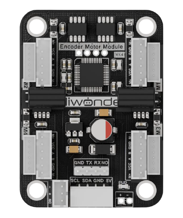
The Hiwonder 4 Channel Motor Driver is a versatile and efficient motor control module designed to drive up to four DC motors or two stepper motors simultaneously. It provides the necessary current and voltage to operate motors in a wide range of applications, including robotics, automation systems, and DIY projects. This motor driver is ideal for hobbyists and professionals alike, offering reliable performance and ease of integration into various projects.
Explore Projects Built with Hiwonder 4 channel motor driver
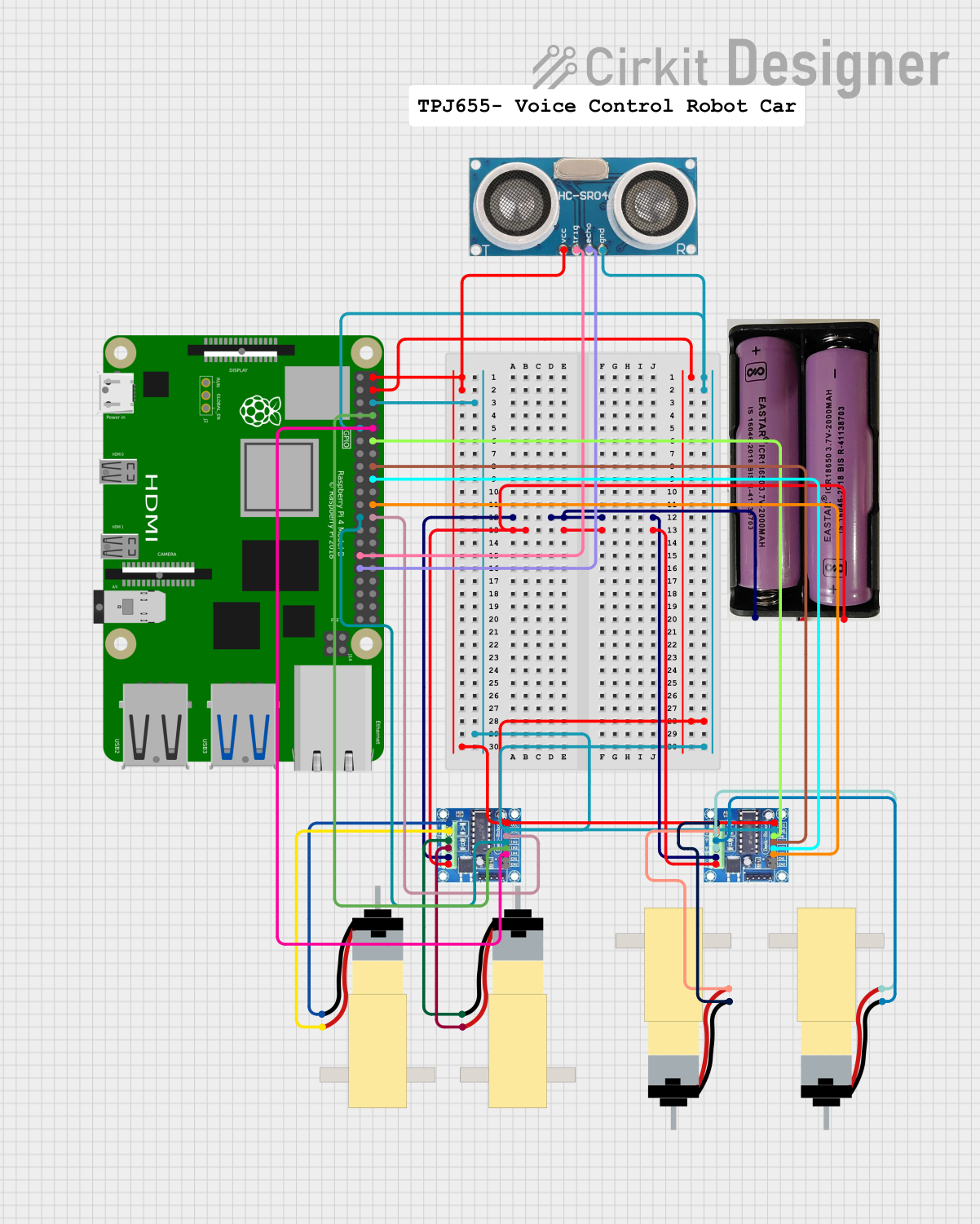
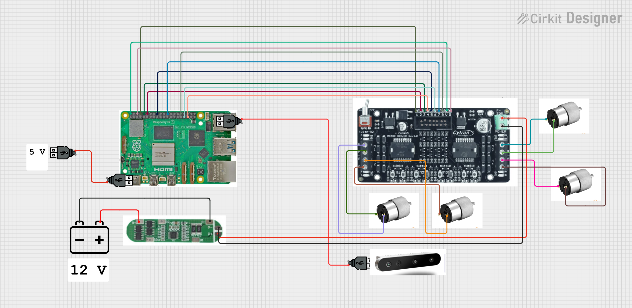
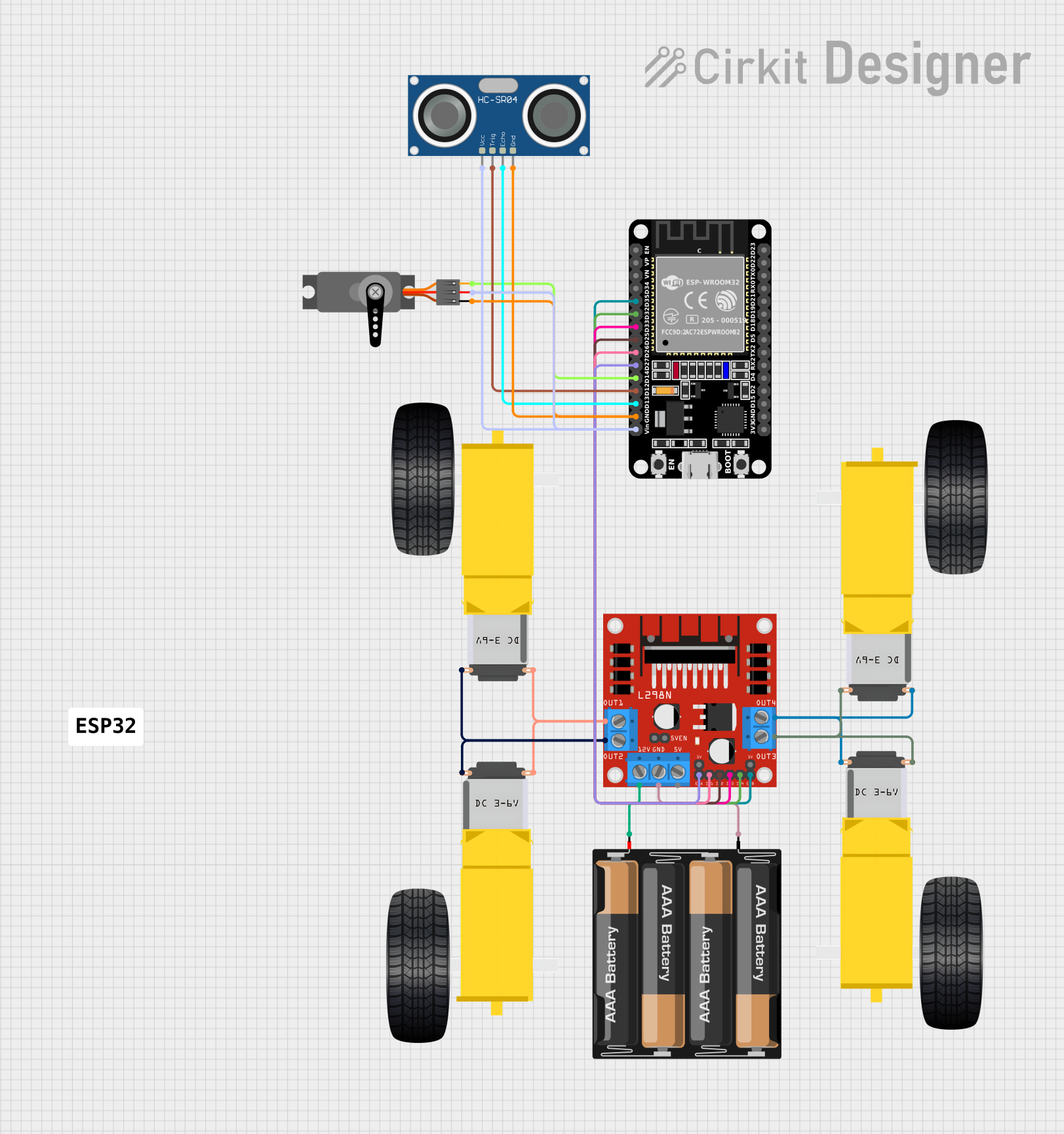
Explore Projects Built with Hiwonder 4 channel motor driver
Common Applications
- Robotics (e.g., robotic arms, mobile robots)
- Automation systems
- Conveyor belts
- DIY motorized projects
- Educational electronics projects
Technical Specifications
Below are the key technical details of the Hiwonder 4 Channel Motor Driver:
| Specification | Details |
|---|---|
| Manufacturer | Hiwonder |
| Part ID | Not specified |
| Operating Voltage | 6V to 12V |
| Maximum Output Current | 2A per channel |
| Number of Channels | 4 (for DC motors) or 2 (for stepper motors) |
| Control Interface | PWM and direction control |
| Logic Voltage | 3.3V or 5V compatible |
| Dimensions | 60mm x 50mm x 15mm |
| Weight | 30g |
| Protection Features | Overcurrent and thermal protection |
Pin Configuration and Descriptions
The Hiwonder 4 Channel Motor Driver has the following pin layout:
Power and Motor Connections
| Pin Name | Description |
|---|---|
| VM | Motor power supply (6V to 12V) |
| GND | Ground connection |
| M1A, M1B | Output terminals for Motor 1 |
| M2A, M2B | Output terminals for Motor 2 |
| M3A, M3B | Output terminals for Motor 3 |
| M4A, M4B | Output terminals for Motor 4 |
Control Pins
| Pin Name | Description |
|---|---|
| EN1, EN2 | Enable pins for Motor 1 and Motor 2 |
| EN3, EN4 | Enable pins for Motor 3 and Motor 4 |
| IN1, IN2 | Control pins for Motor 1 direction |
| IN3, IN4 | Control pins for Motor 2 direction |
| IN5, IN6 | Control pins for Motor 3 direction |
| IN7, IN8 | Control pins for Motor 4 direction |
Usage Instructions
How to Use the Component in a Circuit
- Power Supply: Connect the VM pin to a power source (6V to 12V) and the GND pin to ground.
- Motor Connections: Connect the motor terminals to the corresponding output pins (e.g., M1A and M1B for Motor 1).
- Control Pins: Use the INx pins to control the direction of the motors and the ENx pins to enable or disable the motors.
- Logic Voltage: Ensure the control signals are compatible with the motor driver's logic voltage (3.3V or 5V).
- PWM Control: Use PWM signals on the ENx pins to control the speed of the motors.
Important Considerations and Best Practices
- Current Limitations: Ensure the motors do not exceed the maximum current rating of 2A per channel.
- Heat Dissipation: If the motor driver becomes hot during operation, consider adding a heat sink or fan for cooling.
- Power Supply: Use a stable and sufficient power supply to avoid voltage drops that could affect motor performance.
- Wiring: Double-check all connections to prevent short circuits or incorrect wiring.
Example: Connecting to an Arduino UNO
Below is an example of how to control a DC motor using the Hiwonder 4 Channel Motor Driver and an Arduino UNO:
Circuit Connections
- Connect the VM pin to a 9V power supply and GND to ground.
- Connect Motor 1 to the M1A and M1B terminals.
- Connect EN1 to Arduino pin 9 and IN1/IN2 to Arduino pins 7 and 8, respectively.
Arduino Code
// Define motor control pins
const int EN1 = 9;  // PWM pin for speed control
const int IN1 = 7;  // Direction control pin 1
const int IN2 = 8;  // Direction control pin 2

void setup() {
  // Set motor control pins as outputs
  pinMode(EN1, OUTPUT);
  pinMode(IN1, OUTPUT);
  pinMode(IN2, OUTPUT);
}

void loop() {
  // Rotate motor in one direction
  digitalWrite(IN1, HIGH);  // Set IN1 high
  digitalWrite(IN2, LOW);   // Set IN2 low
  analogWrite(EN1, 128);    // Set speed to 50% (PWM value: 128)
  delay(2000);              // Run for 2 seconds

  // Stop the motor
  analogWrite(EN1, 0);      // Set speed to 0
  delay(1000);              // Wait for 1 second

  // Rotate motor in the opposite direction
  digitalWrite(IN1, LOW);   // Set IN1 low
  digitalWrite(IN2, HIGH);  // Set IN2 high
  analogWrite(EN1, 128);    // Set speed to 50% (PWM value: 128)
  delay(2000);              // Run for 2 seconds

  // Stop the motor
  analogWrite(EN1, 0);      // Set speed to 0
  delay(1000);              // Wait for 1 second
}
Troubleshooting and FAQs
Common Issues
Motor Not Spinning
- Cause: Incorrect wiring or insufficient power supply.
- Solution: Verify all connections and ensure the power supply meets the voltage and current requirements.
Motor Spins in the Wrong Direction
- Cause: Control pins (INx) are set incorrectly.
- Solution: Swap the HIGH/LOW states of the INx pins to reverse the motor direction.
Overheating
- Cause: Excessive current draw or prolonged operation at high loads.
- Solution: Use motors within the current rating and add cooling if necessary.
PWM Control Not Working
- Cause: Incorrect PWM pin configuration or incompatible logic voltage.
- Solution: Ensure the ENx pins are connected to PWM-capable pins on the microcontroller and verify logic voltage compatibility.
FAQs
Can I use this motor driver with a Raspberry Pi? Yes, the motor driver is compatible with 3.3V logic, making it suitable for use with a Raspberry Pi.
What happens if I connect more than 2A to a single channel? The motor driver includes overcurrent protection, but exceeding the current limit may cause the driver to shut down or become damaged.
Can I control stepper motors with this driver? Yes, the driver supports up to two stepper motors. You will need to configure the control pins accordingly.
Is it possible to daisy-chain multiple motor drivers? Yes, you can use multiple motor drivers in a system, but ensure each driver has its own power supply and control signals.