
How to Use Audio Module: Examples, Pinouts, and Specs
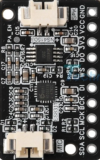
 Design with Audio Module in Cirkit Designer
Introduction
An audio module is a versatile electronic component designed to process, amplify, or generate audio signals. These modules are commonly used in applications such as sound synthesis, audio playback, and effects processing. They are integral to music production, sound design, and various audio-based projects. Audio modules can range from simple amplifiers to complex digital signal processors, making them suitable for both hobbyists and professionals.
Explore Projects Built with Audio Module
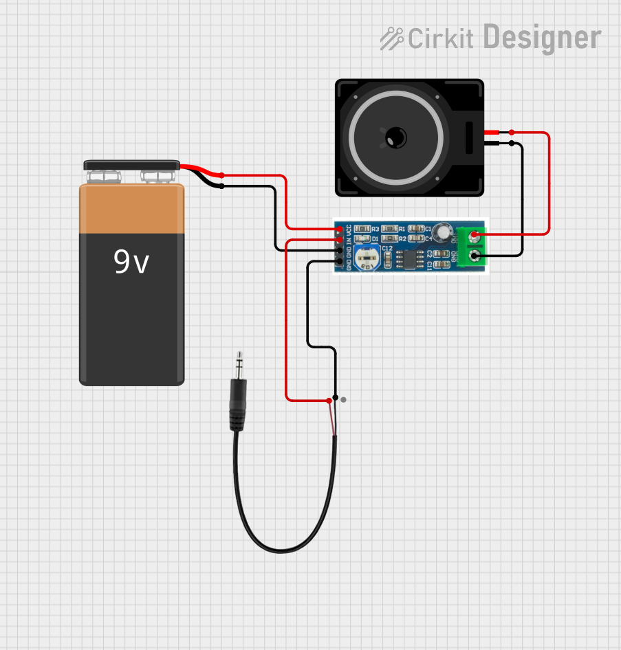 Open Project in Cirkit Designer
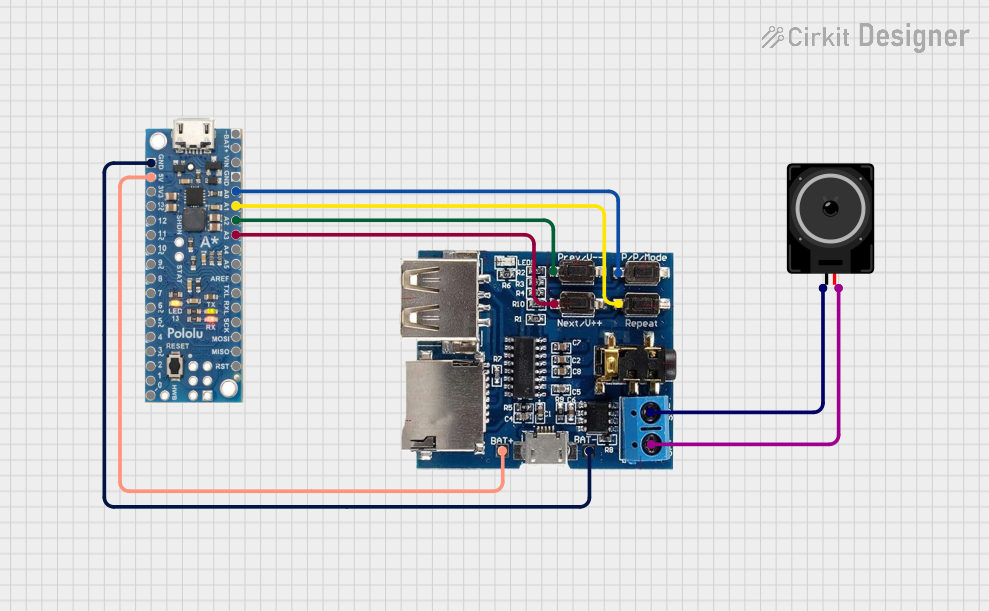 Open Project in Cirkit Designer
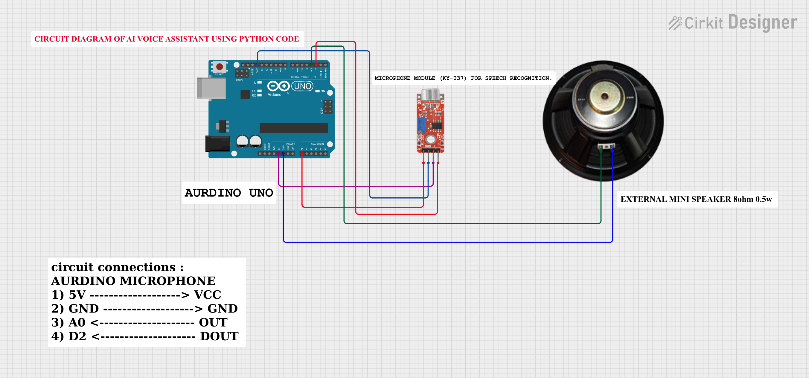 Open Project in Cirkit Designer
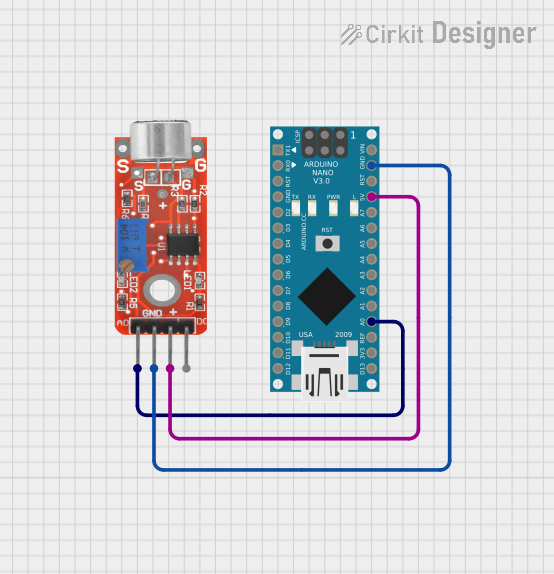 Open Project in Cirkit Designer
Explore Projects Built with Audio Module
Open Project in Cirkit DesignerOpen Project in Cirkit DesignerOpen Project in Cirkit DesignerOpen Project in Cirkit DesignerCommon Applications:
- Music production and sound design
- Audio playback in embedded systems
- Voice recording and playback in IoT devices
- Sound effects generation for robotics and toys
- Audio signal amplification for speakers or headphones
Technical Specifications
Below are the general technical specifications for a typical audio module. Note that specific models may vary, so always refer to the datasheet of your particular module.
Key Specifications:
- Operating Voltage: 3.3V to 5V DC
- Output Power: Up to 3W (depending on the module)
- Audio Input: Analog or digital (e.g., I2S, AUX)
- Audio Output: Speaker terminals or headphone jack
- Signal-to-Noise Ratio (SNR): ≥ 90 dB
- Frequency Response: 20 Hz to 20 kHz
- Impedance: 4Ω to 8Ω (for speakers)
Pin Configuration and Descriptions:
| Pin Name | Description |
|---|---|
| VCC | Power supply input (3.3V to 5V DC) |
| GND | Ground connection |
| IN+ | Positive audio input signal |
| IN- | Negative audio input signal (optional) |
| OUT+ | Positive audio output to speaker/headphones |
| OUT- | Negative audio output to speaker/headphones |
| EN | Enable pin (active HIGH to power the module) |
| DATA | Digital audio input (e.g., I2S, optional) |
Usage Instructions
How to Use the Audio Module in a Circuit:
- Power the Module: Connect the VCC pin to a 3.3V or 5V DC power source and the GND pin to the ground.
- Connect Audio Input:
- For analog input, connect the audio source (e.g., AUX cable or microphone) to the IN+ and IN- pins.
- For digital input, connect the DATA pin to a microcontroller or digital audio source.
- Connect Audio Output: Attach a speaker or headphones to the OUT+ and OUT- pins. Ensure the impedance matches the module's specifications.
- Enable the Module: If the module has an enable pin (EN), set it HIGH to activate the module.
- Adjust Volume (if applicable): Some modules include a potentiometer or software control for volume adjustment.
Important Considerations:
- Power Supply: Ensure the power supply voltage matches the module's requirements to avoid damage.
- Heat Dissipation: For high-power modules, consider adding a heat sink or ensuring proper ventilation.
- Signal Integrity: Use shielded cables for audio input and output to minimize noise and interference.
- Speaker Impedance: Match the speaker impedance to the module's specifications to prevent overloading.
Example: Using an Audio Module with Arduino UNO
Below is an example of connecting an audio module to an Arduino UNO for basic audio playback using PWM.
Circuit Connections:
- Connect the VCC and GND pins of the audio module to the 5V and GND pins of the Arduino.
- Connect the IN+ pin of the audio module to Arduino pin 9 (PWM output).
- Connect a speaker to the OUT+ and OUT- pins of the audio module.
Arduino Code:
// Simple Arduino code to generate a tone using PWM for an audio module

const int audioPin = 9; // PWM pin connected to the audio module's IN+ pin

void setup() {
  pinMode(audioPin, OUTPUT); // Set the audio pin as an output
}

void loop() {
  // Generate a 1 kHz tone for 500 ms
  tone(audioPin, 1000, 500);
  delay(1000); // Wait for 1 second before repeating
}
Troubleshooting and FAQs
Common Issues and Solutions:
No Sound Output:
- Verify the power supply voltage and connections.
- Check if the enable pin (EN) is set HIGH (if applicable).
- Ensure the audio input signal is present and properly connected.
Distorted Audio:
- Reduce the input signal amplitude to avoid overdriving the module.
- Check the speaker impedance and ensure it matches the module's specifications.
Excessive Noise or Interference:
- Use shielded cables for audio connections.
- Ensure proper grounding of the circuit.
Module Overheating:
- Check if the speaker impedance is too low.
- Add a heat sink or improve ventilation around the module.
FAQs:
Q: Can I use the audio module with a 12V power supply?
A: No, most audio modules are designed for 3.3V to 5V operation. Using a higher voltage may damage the module.
Q: Can I connect multiple speakers to the module?
A: It depends on the module's output power and design. Check the datasheet for details on supported configurations.
Q: How do I control the volume?
A: Some modules include a built-in potentiometer for volume control. Alternatively, you can adjust the input signal amplitude or use software-based volume control.
This concludes the documentation for the audio module. Always refer to the specific datasheet of your module for precise details and recommendations.