Cirkit Designer Logo
Cirkit Designer
Your all-in-one circuit design IDE
Home / 
Component Documentation

How to Use ACS724 50A Hall Current Sensor: Examples, Pinouts, and Specs

Image of ACS724 50A Hall Current Sensor
Cirkit Designer LogoDesign with ACS724 50A Hall Current Sensor in Cirkit Designer

Introduction

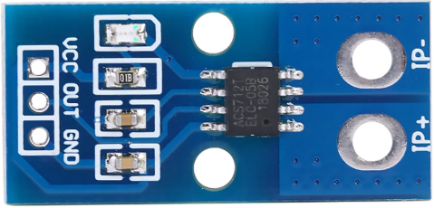
The ACS724 50A Hall Current Sensor is a non-invasive current sensor designed to measure both AC and DC currents up to 50A. It utilizes Hall effect technology to provide an analog output voltage that is proportional to the current being measured. This sensor is highly versatile and can be used in a wide range of applications, including power monitoring, motor control, battery management systems, and overcurrent protection.

Explore Projects Built with ACS724 50A Hall Current Sensor

Use Cirkit Designer to design, explore, and prototype these projects online. Some projects support real-time simulation. Click "Open Project" to start designing instantly!
Wemos S2 Mini Controlled Smart Device with OLED Display, Thermal Printing, and RGB LED Strip
Image of DT NEA - Noah Patel: A project utilizing ACS724 50A Hall Current Sensor in a practical application
This circuit features a Wemos S2 Mini microcontroller that controls a WS2812 RGB LED strip and communicates with a 0.96" OLED display and a 58mm mini thermal printer. The ACS712 Current Sensor is interfaced with the microcontroller to monitor current, and power is managed by a CD42 BMS connected to two 18650 Li-ion batteries, with a USB-C PD Trigger Board for power delivery. The circuit is designed for visual output (LED strip, OLED display), printing capabilities, and current sensing, likely for a portable, battery-powered monitoring and display device.
Cirkit Designer LogoOpen Project in Cirkit Designer
ESP32-Controlled Smart Lighting System with Power Monitoring
Image of Energy Monitoring System: A project utilizing ACS724 50A Hall Current Sensor in a practical application
This circuit appears to be a multi-channel current monitoring system using several ACS712 current sensors to measure the current through different loads, likely bulbs connected to a 220V power source. The current readings from the sensors are digitized by an Adafruit ADS1115 16-bit ADC, which interfaces with an ESP32 microcontroller via I2C communication for further processing or telemetry. A buck converter is used to step down the voltage to power the ESP32 and the sensors, and the system is powered through a 2.1mm DC barrel jack, indicating it is designed for external power supply.
Cirkit Designer LogoOpen Project in Cirkit Designer
ESP32-Based Current Monitoring and Temperature Sensing System
Image of SISTEMA DE MONITOREO: A project utilizing ACS724 50A Hall Current Sensor in a practical application
This circuit is designed to measure current using an ACS712 Current Sensor and temperature using a DS18B20 sensor, with an ESP32 microcontroller to process and possibly communicate the sensor data. The ACS712 sensor output is connected to one of the ESP32's analog input pins (D34), while the DS18B20's signal line is interfaced with a digital input pin (D23) through a pull-up resistor (4.7k Ohms). The ESP32 is powered through its Vin pin, and both sensors share a common ground with the ESP32.
Cirkit Designer LogoOpen Project in Cirkit Designer
Wi-Fi Controlled Power Monitoring and Relay System using ESP8266, ACS712, and ZMPT101B
Image of LOAD MONITORING: A project utilizing ACS724 50A Hall Current Sensor in a practical application
This circuit is designed for monitoring electrical parameters using an ESP8266 microcontroller. It includes an ACS712 current sensor and a ZMPT101B voltage sensor to measure current and voltage, respectively, with the data being multiplexed through a CD4051 multiplexer and controlled by the ESP8266. Additionally, a 5V relay is included for switching purposes, controlled by the ESP8266.
Cirkit Designer LogoOpen Project in Cirkit Designer

Explore Projects Built with ACS724 50A Hall Current Sensor

Use Cirkit Designer to design, explore, and prototype these projects online. Some projects support real-time simulation. Click "Open Project" to start designing instantly!
Image of DT NEA - Noah Patel: A project utilizing ACS724 50A Hall Current Sensor in a practical application
Wemos S2 Mini Controlled Smart Device with OLED Display, Thermal Printing, and RGB LED Strip
This circuit features a Wemos S2 Mini microcontroller that controls a WS2812 RGB LED strip and communicates with a 0.96" OLED display and a 58mm mini thermal printer. The ACS712 Current Sensor is interfaced with the microcontroller to monitor current, and power is managed by a CD42 BMS connected to two 18650 Li-ion batteries, with a USB-C PD Trigger Board for power delivery. The circuit is designed for visual output (LED strip, OLED display), printing capabilities, and current sensing, likely for a portable, battery-powered monitoring and display device.
Cirkit Designer LogoOpen Project in Cirkit Designer
Image of Energy Monitoring System: A project utilizing ACS724 50A Hall Current Sensor in a practical application
ESP32-Controlled Smart Lighting System with Power Monitoring
This circuit appears to be a multi-channel current monitoring system using several ACS712 current sensors to measure the current through different loads, likely bulbs connected to a 220V power source. The current readings from the sensors are digitized by an Adafruit ADS1115 16-bit ADC, which interfaces with an ESP32 microcontroller via I2C communication for further processing or telemetry. A buck converter is used to step down the voltage to power the ESP32 and the sensors, and the system is powered through a 2.1mm DC barrel jack, indicating it is designed for external power supply.
Cirkit Designer LogoOpen Project in Cirkit Designer
Image of SISTEMA DE MONITOREO: A project utilizing ACS724 50A Hall Current Sensor in a practical application
ESP32-Based Current Monitoring and Temperature Sensing System
This circuit is designed to measure current using an ACS712 Current Sensor and temperature using a DS18B20 sensor, with an ESP32 microcontroller to process and possibly communicate the sensor data. The ACS712 sensor output is connected to one of the ESP32's analog input pins (D34), while the DS18B20's signal line is interfaced with a digital input pin (D23) through a pull-up resistor (4.7k Ohms). The ESP32 is powered through its Vin pin, and both sensors share a common ground with the ESP32.
Cirkit Designer LogoOpen Project in Cirkit Designer
Image of LOAD MONITORING: A project utilizing ACS724 50A Hall Current Sensor in a practical application
Wi-Fi Controlled Power Monitoring and Relay System using ESP8266, ACS712, and ZMPT101B
This circuit is designed for monitoring electrical parameters using an ESP8266 microcontroller. It includes an ACS712 current sensor and a ZMPT101B voltage sensor to measure current and voltage, respectively, with the data being multiplexed through a CD4051 multiplexer and controlled by the ESP8266. Additionally, a 5V relay is included for switching purposes, controlled by the ESP8266.
Cirkit Designer LogoOpen Project in Cirkit Designer

Common Applications and Use Cases

  • Power monitoring in industrial and residential systems
  • Motor current sensing in robotics and automation
  • Battery management systems for electric vehicles
  • Overcurrent protection in power supplies
  • Renewable energy systems (e.g., solar inverters)

Technical Specifications

The following table outlines the key technical details of the ACS724 50A Hall Current Sensor:

Parameter Value
Manufacturer Generic
Part ID ACS724 50A
Current Sensing Range ±50A
Supply Voltage (Vcc) 4.5V to 5.5V
Output Voltage Range 0.5V to 4.5V
Sensitivity 40mV/A
Bandwidth 120 kHz
Response Time 5 µs
Operating Temperature Range -40°C to +150°C
Isolation Voltage 2.1 kV RMS

Pin Configuration and Descriptions

The ACS724 50A sensor has a simple pinout, as shown in the table below:

Pin Name Description
1 Vcc Power supply input (4.5V to 5.5V). Connect to the 5V pin of your microcontroller.
2 OUT Analog output voltage proportional to the sensed current.
3 GND Ground connection. Connect to the ground of your circuit.
4 IP+ Current input terminal (positive). Connect to the high side of the current path.
5 IP- Current input terminal (negative). Connect to the low side of the current path.

Usage Instructions

How to Use the ACS724 50A in a Circuit

  1. Power the Sensor: Connect the Vcc pin to a 5V power supply and the GND pin to the ground of your circuit.
  2. Connect the Current Path:
    • Pass the current-carrying conductor through the IP+ and IP- terminals of the sensor.
    • Ensure the current direction matches the sensor's orientation for accurate readings.
  3. Read the Output Voltage:
    • The OUT pin provides an analog voltage proportional to the sensed current.
    • Use an analog-to-digital converter (ADC) on a microcontroller (e.g., Arduino UNO) to read the output voltage.

Important Considerations and Best Practices

  • Calibration: The sensor's output voltage at 0A is typically 2.5V. Use this as a reference point for calibration.
  • Filtering: Add a capacitor (e.g., 1 µF) between the OUT pin and GND to reduce noise in the output signal.
  • Current Range: Ensure the current being measured does not exceed ±50A to avoid damaging the sensor.
  • Isolation: The sensor provides electrical isolation between the current path and the output signal, making it safe for high-voltage applications.

Example Code for Arduino UNO

The following code demonstrates how to interface the ACS724 50A sensor with an Arduino UNO to measure current:

// Define the analog pin connected to the ACS724 OUT pin
const int sensorPin = A0;

// Define the sensor's sensitivity (40mV/A for ACS724 50A)
const float sensitivity = 0.04; // Sensitivity in V/A

// Define the reference voltage at 0A (typically 2.5V)
const float zeroCurrentVoltage = 2.5;

void setup() {
  Serial.begin(9600); // Initialize serial communication
}

void loop() {
  // Read the analog value from the sensor
  int sensorValue = analogRead(sensorPin);

  // Convert the analog value to voltage (assuming 5V reference)
  float sensorVoltage = sensorValue * (5.0 / 1023.0);

  // Calculate the current in Amperes
  float current = (sensorVoltage - zeroCurrentVoltage) / sensitivity;

  // Print the current to the Serial Monitor
  Serial.print("Current: ");
  Serial.print(current);
  Serial.println(" A");

  delay(500); // Wait for 500ms before the next reading
}

Notes on the Code

  • Ensure the Arduino's reference voltage is set to 5V for accurate ADC readings.
  • The zeroCurrentVoltage value may vary slightly between sensors. Measure the output voltage at 0A and adjust this value accordingly.

Troubleshooting and FAQs

Common Issues and Solutions

  1. No Output Voltage or Incorrect Readings

    • Cause: Incorrect wiring or loose connections.
    • Solution: Double-check all connections, especially the Vcc, GND, and OUT pins.
  2. High Noise in Output Signal

    • Cause: Electrical noise or lack of filtering.
    • Solution: Add a capacitor (e.g., 1 µF) between the OUT pin and GND to filter noise.
  3. Output Voltage Does Not Match Expected Values

    • Cause: Calibration error or incorrect sensitivity value.
    • Solution: Verify the zeroCurrentVoltage and sensitivity values. Recalibrate if necessary.
  4. Sensor Overheating

    • Cause: Current exceeds the ±50A limit.
    • Solution: Ensure the current being measured is within the sensor's specified range.

FAQs

Q: Can the ACS724 50A measure both AC and DC currents?
A: Yes, the sensor can measure both AC and DC currents up to ±50A.

Q: What is the typical output voltage at 0A?
A: The typical output voltage at 0A is 2.5V, but this may vary slightly between sensors.

Q: Is the sensor safe for high-voltage applications?
A: Yes, the ACS724 provides electrical isolation up to 2.1 kV RMS, making it suitable for high-voltage applications.

Q: Can I use this sensor with a 3.3V microcontroller?
A: The sensor requires a 5V power supply, but the output voltage can be read by a 3.3V ADC if the voltage levels are compatible. Use a voltage divider if necessary.

Q: How do I improve the accuracy of the sensor?
A: Calibrate the sensor by measuring the output voltage at 0A and adjusting the zeroCurrentVoltage value in your code. Additionally, use proper filtering to reduce noise.