
How to Use ESC 90A: Examples, Pinouts, and Specs
 Design with ESC 90A in Cirkit Designer
Introduction
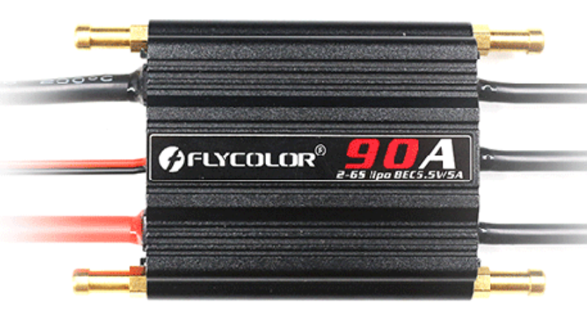
The FLYCOLOR 90A Electronic Speed Controller (ESC) is a high-performance component designed to control the speed, direction, and braking of brushless motors. With a current rating of 90 Amperes, this ESC is ideal for applications requiring precise throttle control, such as remote-controlled (RC) vehicles, drones, boats, and other hobbyist projects. Its robust design ensures reliable operation under demanding conditions, making it a popular choice for enthusiasts and professionals alike.
Explore Projects Built with ESC 90A
 Open Project in Cirkit Designer
 Open Project in Cirkit Designer
 Open Project in Cirkit Designer
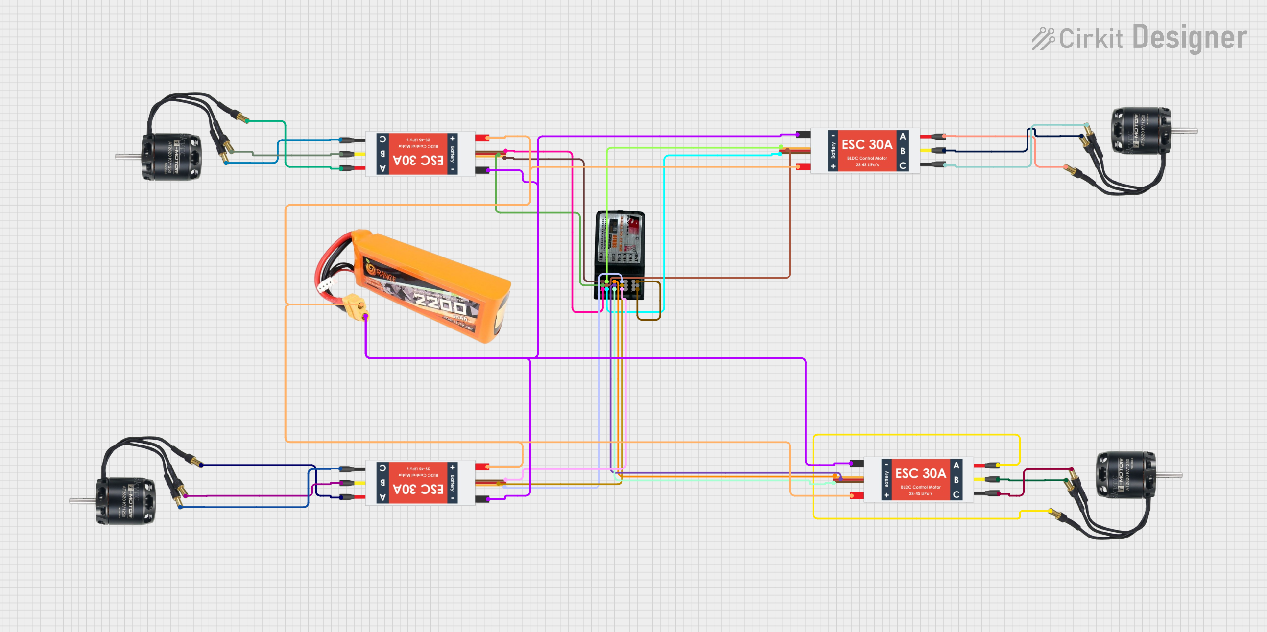 Open Project in Cirkit Designer
Explore Projects Built with ESC 90A
Open Project in Cirkit DesignerOpen Project in Cirkit DesignerOpen Project in Cirkit DesignerOpen Project in Cirkit DesignerCommon Applications
- RC drones and quadcopters
- RC cars and trucks
- RC boats
- Robotics and automation projects
- Electric-powered model aircraft
Technical Specifications
The following table outlines the key technical details of the FLYCOLOR 90A ESC:
| Parameter | Specification |
|---|---|
| Manufacturer | FLYCOLOR |
| Part ID | 90A |
| Continuous Current | 90 Amperes |
| Peak Current | 120 Amperes (for 10 seconds) |
| Input Voltage Range | 2S–6S LiPo (7.4V–22.2V) |
| Motor Compatibility | Brushless motors (sensorless) |
| BEC Output | 5V/3A (linear mode) |
| Throttle Signal Range | 1ms–2ms (standard PWM) |
| Weight | ~65 grams |
| Dimensions | 70mm x 35mm x 15mm |
| Operating Temperature | -10°C to 60°C |
| Protection Features | Overcurrent, overheat, and low-voltage cutoff |
Pin Configuration and Descriptions
The FLYCOLOR 90A ESC has the following connections:
| Pin/Connector | Description |
|---|---|
| Power Input (Red/Black) | Connect to the positive (red) and negative (black) terminals of the battery. |
| Motor Output (3 Wires) | Connect to the three wires of the brushless motor. The order determines motor direction. |
| Signal Input (White) | Connect to the PWM signal pin of the flight controller or receiver. |
| Ground (Black) | Connect to the ground pin of the flight controller or receiver. |
| BEC Output (Red/Black) | Provides 5V/3A power for external devices like receivers or servos. |
Usage Instructions
How to Use the ESC in a Circuit
- Connect the Power Source: Attach the ESC's power input wires (red and black) to the battery terminals. Ensure the voltage matches the ESC's input range (2S–6S LiPo).
- Connect the Motor: Attach the three motor output wires to the brushless motor. If the motor spins in the wrong direction, swap any two wires.
- Connect the Signal Input: Connect the white signal wire to the PWM output pin of your flight controller or RC receiver.
- Connect the Ground: Ensure the ESC's ground wire is connected to the ground of the flight controller or receiver.
- Calibrate the Throttle:
- Power on the transmitter and set the throttle to maximum.
- Power on the ESC while holding the throttle at maximum.
- Wait for the calibration tones, then move the throttle to the minimum position.
- Wait for the confirmation tones indicating successful calibration.
- Secure the ESC: Mount the ESC securely in your vehicle or drone using zip ties or double-sided tape to prevent movement during operation.
Important Considerations and Best Practices
- Cooling: Ensure adequate airflow around the ESC to prevent overheating during operation.
- Battery Compatibility: Use only LiPo batteries within the specified voltage range (2S–6S).
- Signal Quality: Use a high-quality PWM signal source to avoid erratic motor behavior.
- Wiring: Keep wires as short as possible to minimize resistance and electromagnetic interference.
- Pre-Flight Check: Always test the motor and ESC setup on the ground before flying or driving.
Example Code for Arduino UNO
The following example demonstrates how to control the ESC using an Arduino UNO:
#include <Servo.h> // Include the Servo library to generate PWM signals

Servo esc; // Create a Servo object to control the ESC

void setup() {
  esc.attach(9); // Attach the ESC signal wire to pin 9
  esc.writeMicroseconds(1000); // Set throttle to minimum (1ms pulse)
  delay(2000); // Wait for the ESC to initialize
}

void loop() {
  esc.writeMicroseconds(1500); // Set throttle to mid-range (1.5ms pulse)
  delay(5000); // Run motor at mid-speed for 5 seconds

  esc.writeMicroseconds(1000); // Set throttle to minimum (stop motor)
  delay(5000); // Wait for 5 seconds before repeating
}
Note: Ensure the ESC is properly calibrated before running the code. Always test the setup without propellers for safety.
Troubleshooting and FAQs
Common Issues and Solutions
Motor Does Not Spin:
- Check all connections, especially the signal wire.
- Ensure the throttle is calibrated correctly.
- Verify the battery voltage is within the ESC's input range.
Motor Spins in the Wrong Direction:
- Swap any two of the three motor output wires.
ESC Overheats:
- Ensure proper airflow around the ESC.
- Verify the motor and propeller are not drawing excessive current.
No Power to Receiver or Servos:
- Check the BEC output connections.
- Ensure the ESC is powered by a compatible battery.
ESC Emits Continuous Beeping:
- This indicates a throttle signal issue. Verify the signal wire is connected to the correct pin on the flight controller or receiver.
FAQs
Q: Can I use this ESC with a brushed motor?
A: No, the FLYCOLOR 90A ESC is designed specifically for brushless motors.
Q: What happens if I exceed the ESC's current rating?
A: The ESC's overcurrent protection will activate, shutting down the motor to prevent damage.
Q: Can I use this ESC with a 7S LiPo battery?
A: No, the ESC supports a maximum of 6S LiPo batteries (22.2V).
Q: How do I update the firmware on this ESC?
A: The FLYCOLOR 90A ESC does not support firmware updates.
By following this documentation, you can effectively integrate the FLYCOLOR 90A ESC into your projects and troubleshoot common issues with ease.