How to Use Adafruit Datalogger Shield v1: Examples, Pinouts, and Specs
Introduction
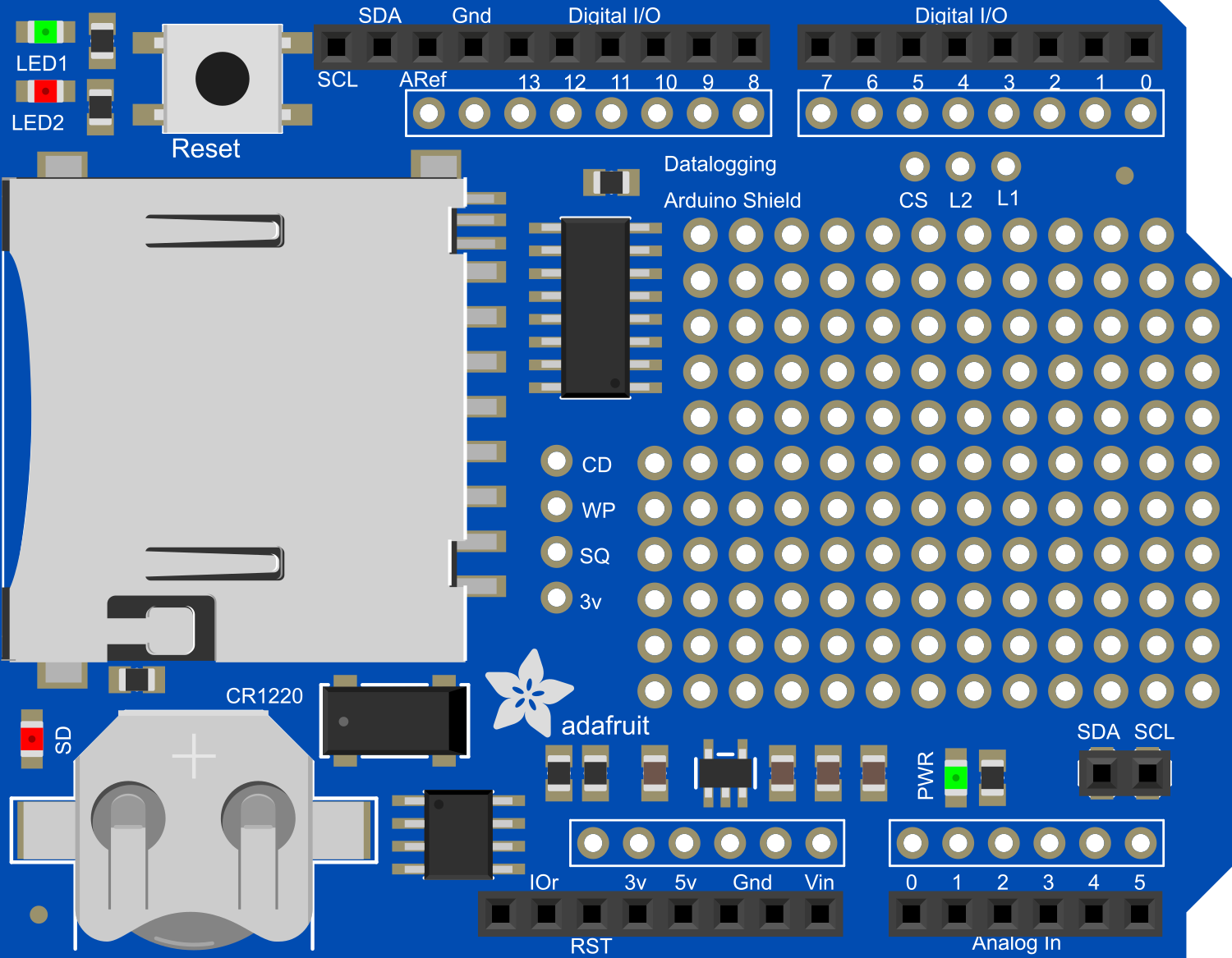
The Adafruit Datalogger Shield v1 is a versatile shield designed to fit on top of an Arduino UNO or similar boards. It provides an easy way to log data from sensors and other inputs to an SD card, making it ideal for remote sensing, weather stations, and other projects where data collection over time is crucial. The shield also includes a real-time clock (RTC) for timestamping the logged data, ensuring accurate timekeeping even when the Arduino is powered off.
Explore Projects Built with Adafruit Datalogger Shield v1
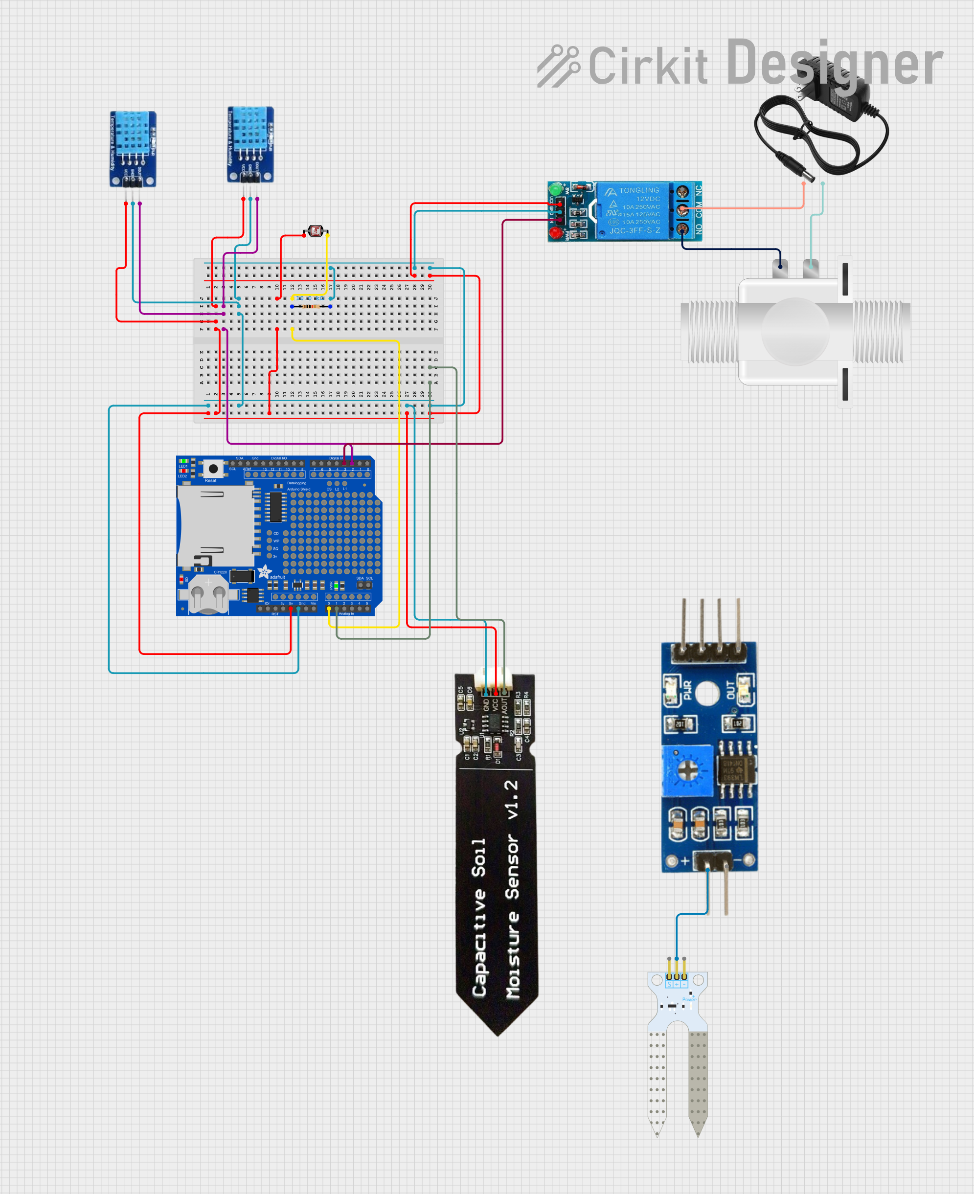
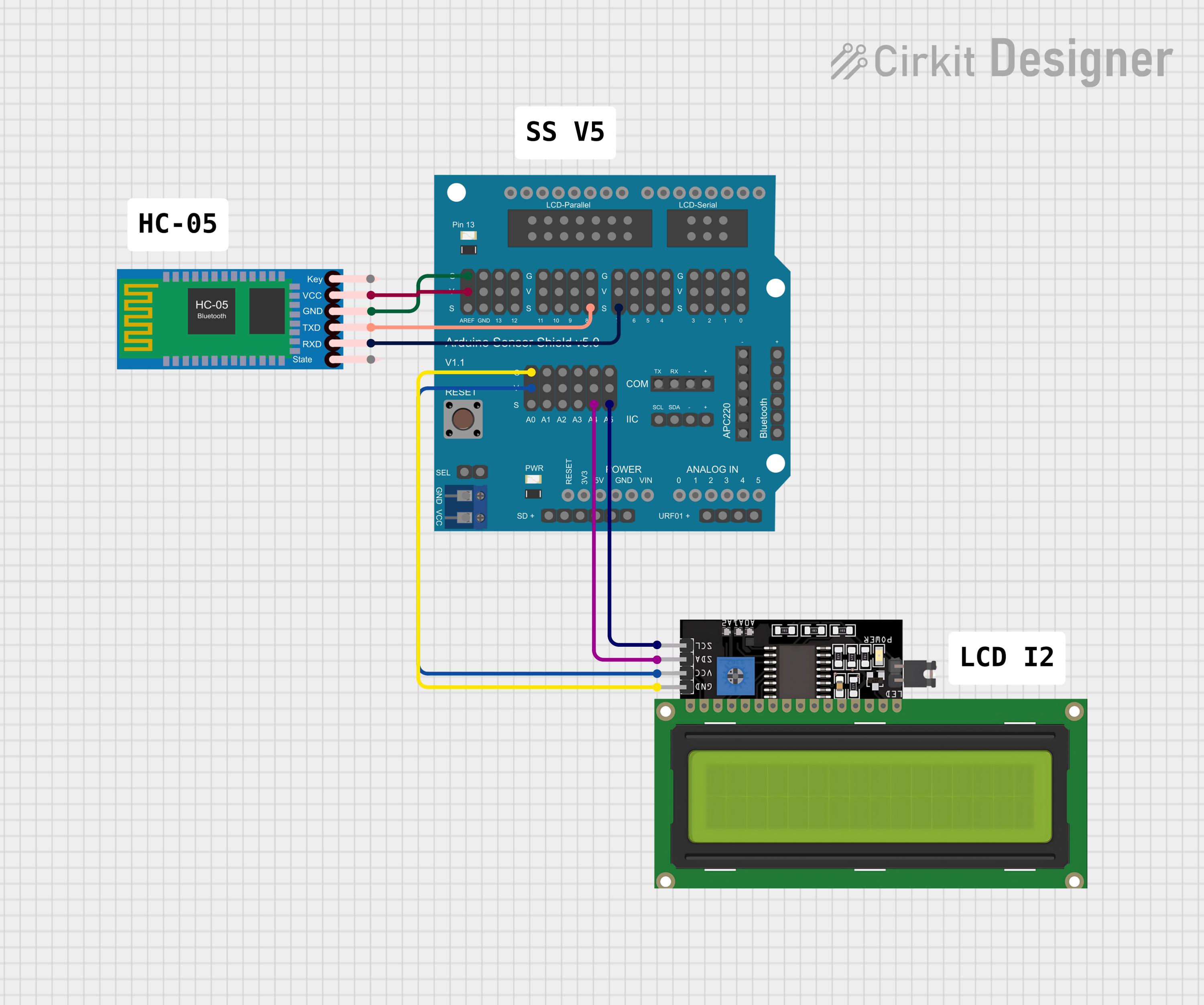
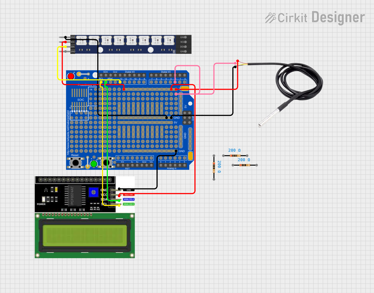
Explore Projects Built with Adafruit Datalogger Shield v1
Common Applications and Use Cases
- Environmental data logging (temperature, humidity, pressure)
- Home automation systems (energy usage, lighting, security logs)
- Scientific experiments (data collection over time)
- Vehicle tracking and telemetry
- Robotics (logging sensor data for analysis)
Technical Specifications
Key Technical Details
- Operating Voltage: 5V (from Arduino board)
- RTC Battery: CR1220 3V coin cell (not included)
- SD Card Interface: Supports SD (Secure Digital) and SDHC cards
- RTC Chip: DS1307
Pin Configuration and Descriptions
| Pin Number | Function | Description |
|---|---|---|
| D10 | CS (Chip Select) | Selects the SD card slot when driven low |
| D11 | MOSI (Master Out) | SPI Master Out, Slave In for SD card communication |
| D12 | MISO (Master In) | SPI Master In, Slave Out for SD card communication |
| D13 | SCK (Clock) | SPI Clock for SD card communication |
| A4 | SDA (Data) | I2C Data for RTC |
| A5 | SCL (Clock) | I2C Clock for RTC |
Usage Instructions
How to Use the Component in a Circuit
- Mounting the Shield: Place the Adafruit Datalogger Shield on top of the Arduino UNO, ensuring that all pins are aligned and fully inserted.
- Inserting the SD Card: Insert an SD or SDHC card into the slot on the shield.
- Installing the RTC Battery: Place a CR1220 coin cell battery into the battery holder to power the RTC.
- Connecting Sensors: Connect sensors or other input devices to the Arduino's analog and digital pins as needed for your project.
Important Considerations and Best Practices
- Power Supply: Ensure that the Arduino board is powered adequately to support the shield and any connected sensors.
- SD Card Formatting: Format the SD card as FAT16 or FAT32 before use.
- RTC Library: Use a compatible RTC library to interface with the DS1307 chip for timekeeping functions.
- Data Logging Frequency: Determine the frequency of data logging based on your application needs and the storage capacity of the SD card.
- Timestamps: Use the RTC to timestamp each data entry for accurate record-keeping.
Example Code for Arduino UNO
#include <Wire.h>
#include <RTClib.h>
#include <SPI.h>
#include <SD.h>

RTC_DS1307 rtc; // Create an RTC object
const int chipSelect = 10; // SD card chip select pin

void setup() {
  Serial.begin(9600);
  // Initialize the RTC
  if (!rtc.begin()) {
    Serial.println("Couldn't find RTC");
    while (1);
  }
  if (!rtc.isrunning()) {
    Serial.println("RTC is NOT running!");
    // Set the date and time at compile time
    rtc.adjust(DateTime(F(__DATE__), F(__TIME__)));
  }
  // Initialize the SD card
  if (!SD.begin(chipSelect)) {
    Serial.println("Initialization failed!");
    return;
  }
  // Create or open the log file
  File logFile = SD.open("datalog.txt", FILE_WRITE);
  if (logFile) {
    DateTime now = rtc.now(); // Get current time
    // Write a header with the current date and time
    logFile.print("Log started on: ");
    logFile.print(now.year(), DEC);
    logFile.print('/');
    logFile.print(now.month(), DEC);
    logFile.print('/');
    logFile.print(now.day(), DEC);
    logFile.print(" ");
    logFile.print(now.hour(), DEC);
    logFile.print(':');
    logFile.print(now.minute(), DEC);
    logFile.print(':');
    logFile.print(now.second(), DEC);
    logFile.println();
    logFile.close(); // Close the file
    Serial.println("Initialization done.");
  } else {
    Serial.println("Error opening datalog.txt");
  }
}

void loop() {
  // Log data at regular intervals
  // This example assumes a sensor reading function called readSensor()
  File logFile = SD.open("datalog.txt", FILE_WRITE);
  if (logFile) {
    DateTime now = rtc.now(); // Get current time
    int sensorValue = readSensor(); // Replace with actual sensor reading
    // Write data with a timestamp
    logFile.print(now.unixtime()); // Unix time as a simple timestamp
    logFile.print(", ");
    logFile.println(sensorValue);
    logFile.close(); // Close the file after writing
  } else {
    Serial.println("Error opening datalog.txt");
  }
  delay(2000); // Wait for 2 seconds before the next log entry
}

int readSensor() {
  // Placeholder for sensor reading logic
  return analogRead(A0); // Example: read from analog pin A0
}
Troubleshooting and FAQs
Common Issues Users Might Face
- SD Card Not Detected: Ensure the card is formatted correctly and properly inserted into the slot.
- RTC Not Keeping Time: Check that the RTC battery is installed and has charge.
- Data Not Logging: Verify that the
datalog.txtfile can be created or opened, and that the SD card is not full.
Solutions and Tips for Troubleshooting
- SD Card Issues: Try a different SD card or reformat the existing one. Make sure the chip select pin is correctly set in the code.
- RTC Issues: Replace the RTC battery if necessary. Use the provided example code to set the time when the RTC is not running.
- File Writing Issues: Check for proper file opening and closing in the code. Ensure there's enough delay between write operations to allow for file saving.
FAQs
Q: Can I use a microSD card with this shield? A: Yes, but you will need a microSD to SD adapter.
Q: How much data can I log? A: It depends on the size of the SD card and the frequency and size of the log entries.
Q: Can I use this shield with other Arduino boards? A: The shield is designed for the Arduino UNO form factor but may be compatible with other boards that share the same pin layout and voltage specifications.