How to Use Volume Control Potentiometer: Examples, Pinouts, and Specs
Introduction
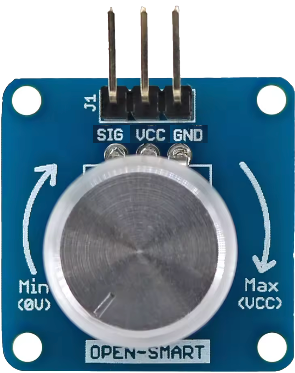
The Volume Control Potentiometer by OPEN-SMART is a variable resistor designed to adjust the level of audio signals in electronic circuits. It allows users to control the volume of sound in devices such as amplifiers, radios, and audio players. This component is widely used in audio systems due to its simplicity, reliability, and precision in controlling signal levels.
Explore Projects Built with Volume Control Potentiometer
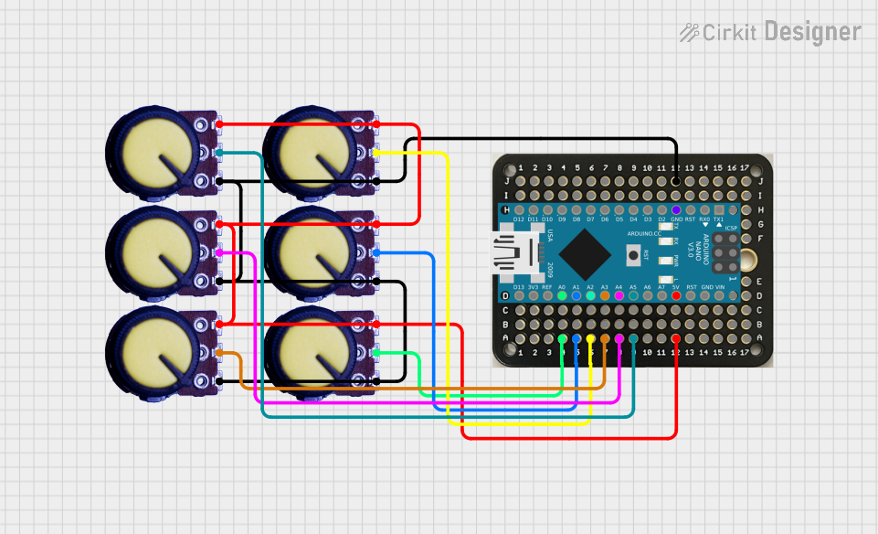
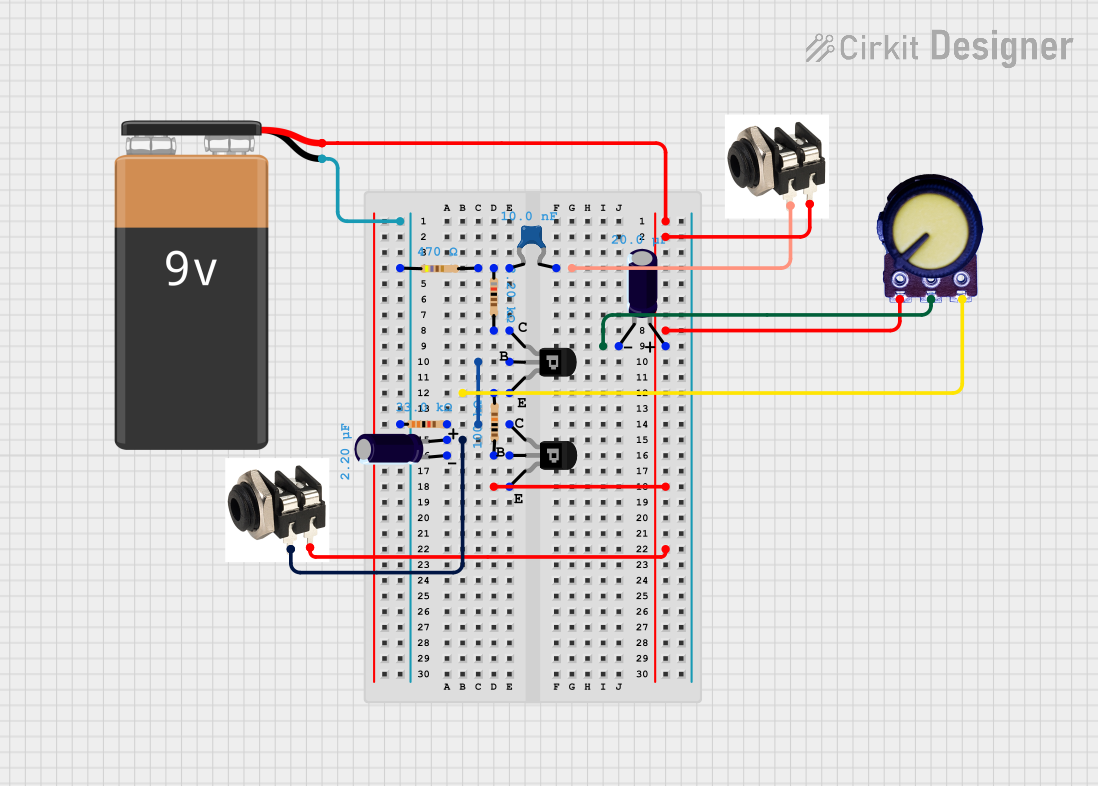
Explore Projects Built with Volume Control Potentiometer
Common Applications and Use Cases
- Audio amplifiers for adjusting speaker volume
- Radios and music players for user-controlled sound levels
- DIY audio projects and custom sound systems
- Signal attenuation in electronic circuits
Technical Specifications
The following table outlines the key technical details of the OPEN-SMART Volume Control Potentiometer:
| Parameter | Specification |
|---|---|
| Resistance Range | 10 kΩ (typical) |
| Tolerance | ±20% |
| Power Rating | 0.2 W |
| Operating Voltage | 0–50 V DC |
| Adjustment Type | Rotary |
| Shaft Length | 15 mm |
| Shaft Diameter | 6 mm |
| Mounting Type | Through-hole |
| Temperature Range | -10°C to +70°C |
Pin Configuration and Descriptions
The potentiometer typically has three pins, as described below:
| Pin | Description |
|---|---|
| Pin 1 | Connects to one end of the resistive track (fixed) |
| Pin 2 | Wiper pin (variable output based on shaft position) |
| Pin 3 | Connects to the other end of the resistive track |
Usage Instructions
How to Use the Component in a Circuit
- Identify the Pins: Locate the three pins on the potentiometer. Pin 1 and Pin 3 are the fixed ends of the resistive track, while Pin 2 is the wiper.
- Connect the Circuit:
- Connect Pin 1 to the input signal or voltage source.
- Connect Pin 3 to ground or the other end of the circuit.
- Connect Pin 2 to the output where the variable signal is required.
- Adjust the Shaft: Rotate the shaft to vary the resistance between Pin 1 and Pin 2, or Pin 2 and Pin 3. This adjusts the output signal level.
Important Considerations and Best Practices
- Power Rating: Ensure the power dissipation across the potentiometer does not exceed its 0.2 W rating to avoid damage.
- Mechanical Stress: Avoid applying excessive force to the shaft to prevent mechanical failure.
- Noise Reduction: For audio applications, use a capacitor across the output to reduce noise and improve signal stability.
- Mounting: Secure the potentiometer firmly to prevent movement during operation.
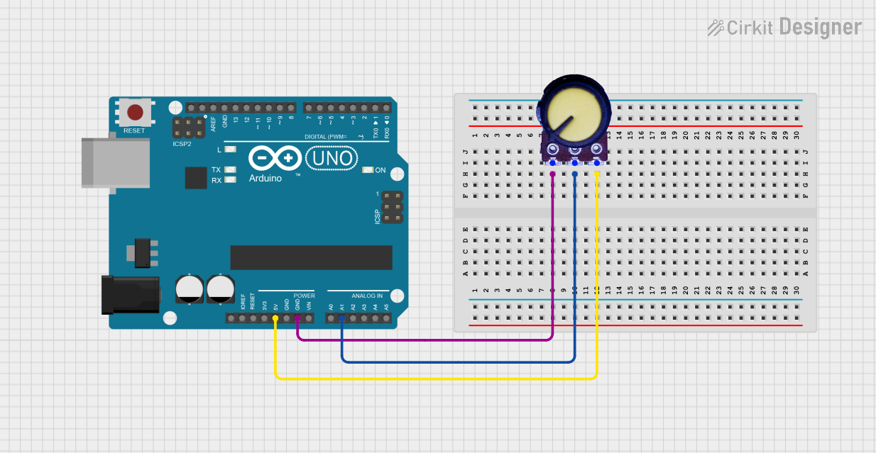
Example: Connecting to an Arduino UNO
The potentiometer can be used with an Arduino UNO to read analog values and control audio levels. Below is an example code snippet:
// Example: Reading potentiometer values with Arduino UNO
const int potPin = A0;  // Connect Pin 2 (wiper) of the potentiometer to A0
int potValue = 0;       // Variable to store the potentiometer value

void setup() {
  Serial.begin(9600);   // Initialize serial communication at 9600 baud
}

void loop() {
  potValue = analogRead(potPin);  // Read the analog value from the potentiometer
  Serial.print("Potentiometer Value: ");
  Serial.println(potValue);       // Print the value to the Serial Monitor
  delay(100);                     // Small delay for stability
}
Wiring Instructions:
- Connect Pin 1 of the potentiometer to 5V on the Arduino.
- Connect Pin 3 to GND on the Arduino.
- Connect Pin 2 (wiper) to the analog input pin A0.
Troubleshooting and FAQs
Common Issues Users Might Face
No Output Signal:
- Cause: Incorrect wiring of the potentiometer pins.
- Solution: Verify the connections. Ensure Pin 1 is connected to the input signal, Pin 3 to ground, and Pin 2 to the output.
Inconsistent or Noisy Output:
- Cause: Dust or wear on the resistive track.
- Solution: Clean the potentiometer with contact cleaner or replace it if worn out.
Overheating:
- Cause: Exceeding the power rating of the potentiometer.
- Solution: Ensure the power dissipation is within the 0.2 W limit.
Mechanical Failure:
- Cause: Excessive force applied to the shaft.
- Solution: Handle the potentiometer gently and avoid over-tightening during installation.
FAQs
Q1: Can this potentiometer be used for non-audio applications?
Yes, it can be used in any circuit requiring variable resistance, such as LED dimming or motor speed control.
Q2: How do I know the resistance value of the potentiometer?
The resistance value (e.g., 10 kΩ) is typically printed on the body of the potentiometer.
Q3: Can I use this potentiometer with a 3.3V system?
Yes, the potentiometer is compatible with both 3.3V and 5V systems, as long as the power dissipation does not exceed 0.2 W.
Q4: What is the lifespan of this potentiometer?
The lifespan depends on usage but is typically rated for thousands of cycles of adjustment.