Cirkit Designer Logo
Cirkit Designer
Your all-in-one circuit design IDE
Home / 
Component Documentation

How to Use Adafruit Feather 32u4 RFM9x: Examples, Pinouts, and Specs

Image of Adafruit Feather 32u4 RFM9x
Cirkit Designer LogoDesign with Adafruit Feather 32u4 RFM9x in Cirkit Designer

Introduction

The Adafruit Feather 32u4 RFM9x is a versatile and compact development board that combines the power of the ATmega32u4 microcontroller with the long-range wireless capabilities of the RFM9x LoRa radio module. This board is part of the Feather ecosystem, designed by Adafruit for portability, ease of use, and interoperability with a wide range of FeatherWings (add-on boards). It is ideal for applications such as remote sensors, home automation, and IoT devices where long-range communication is essential.

Explore Projects Built with Adafruit Feather 32u4 RFM9x

Use Cirkit Designer to design, explore, and prototype these projects online. Some projects support real-time simulation. Click "Open Project" to start designing instantly!
ESP32-Controlled LoRa Communication Module
Image of receiver: A project utilizing Adafruit Feather 32u4 RFM9x in a practical application
This circuit connects an ESP32 microcontroller to an Adafruit RFM9x LoRa Radio module for wireless communication. The ESP32's GPIO pins are wired to the LoRa module's SPI interface (MOSI, MISO, SCK, CS), interrupt (DIO0), and reset (RST) to enable data transmission and reception over LoRa. The ESP32 also provides power (3V3) and ground (GND) to the LoRa module.
Cirkit Designer LogoOpen Project in Cirkit Designer
Arduino MKR WiFi 1010 and Adafruit RFM9x LoRa Radio Communication System
Image of 1010: A project utilizing Adafruit Feather 32u4 RFM9x in a practical application
This circuit connects an Adafruit RFM9x LoRa Radio module to an Arduino MKR WiFi 1010 for wireless communication capabilities. The LoRa module's SPI interface (MOSI, MISO, SCK, CS) is connected to the corresponding SPI pins on the Arduino, allowing for serial data transfer between the devices. Additionally, the LoRa module's reset (RST) and interrupt (DIO0) pins are connected to digital pins on the Arduino for control and asynchronous communication.
Cirkit Designer LogoOpen Project in Cirkit Designer
Biometric and RFID Security System with Dual Adafruit Feather nRF52840 Controllers
Image of Rfid access control: A project utilizing Adafruit Feather 32u4 RFM9x in a practical application
This circuit features two Adafruit Feather nRF52840 microcontrollers, each interfaced with an RFID-RC522 module for RFID communication and an AT24C256 external EEPROM for additional memory storage. One of the microcontrollers is also connected to an R307 Fingerprint Sensor for biometric input, and both microcontrollers are powered by a shared power supply and a coin cell breakout for backup or RTC power. The circuit is likely designed for secure access control or identification purposes, utilizing both RFID and fingerprint authentication, with data storage capabilities.
Cirkit Designer LogoOpen Project in Cirkit Designer
Dual-Mode LoRa and GSM Communication Device with ESP32
Image of modul gateway: A project utilizing Adafruit Feather 32u4 RFM9x in a practical application
This circuit features an ESP32 Devkit V1 microcontroller interfaced with an RFM95 LoRa transceiver module for long-range communication and a SIM800L GSM module for cellular connectivity. Two LM2596 step-down modules are used to regulate the 12V battery voltage down to 3.3V required by the ESP32, RFM95, and SIM800L. The ESP32 facilitates data exchange between the RFM95 and SIM800L, enabling the system to send/receive data over both LoRa and GSM networks.
Cirkit Designer LogoOpen Project in Cirkit Designer

Explore Projects Built with Adafruit Feather 32u4 RFM9x

Use Cirkit Designer to design, explore, and prototype these projects online. Some projects support real-time simulation. Click "Open Project" to start designing instantly!
Image of receiver: A project utilizing Adafruit Feather 32u4 RFM9x in a practical application
ESP32-Controlled LoRa Communication Module
This circuit connects an ESP32 microcontroller to an Adafruit RFM9x LoRa Radio module for wireless communication. The ESP32's GPIO pins are wired to the LoRa module's SPI interface (MOSI, MISO, SCK, CS), interrupt (DIO0), and reset (RST) to enable data transmission and reception over LoRa. The ESP32 also provides power (3V3) and ground (GND) to the LoRa module.
Cirkit Designer LogoOpen Project in Cirkit Designer
Image of 1010: A project utilizing Adafruit Feather 32u4 RFM9x in a practical application
Arduino MKR WiFi 1010 and Adafruit RFM9x LoRa Radio Communication System
This circuit connects an Adafruit RFM9x LoRa Radio module to an Arduino MKR WiFi 1010 for wireless communication capabilities. The LoRa module's SPI interface (MOSI, MISO, SCK, CS) is connected to the corresponding SPI pins on the Arduino, allowing for serial data transfer between the devices. Additionally, the LoRa module's reset (RST) and interrupt (DIO0) pins are connected to digital pins on the Arduino for control and asynchronous communication.
Cirkit Designer LogoOpen Project in Cirkit Designer
Image of Rfid access control: A project utilizing Adafruit Feather 32u4 RFM9x in a practical application
Biometric and RFID Security System with Dual Adafruit Feather nRF52840 Controllers
This circuit features two Adafruit Feather nRF52840 microcontrollers, each interfaced with an RFID-RC522 module for RFID communication and an AT24C256 external EEPROM for additional memory storage. One of the microcontrollers is also connected to an R307 Fingerprint Sensor for biometric input, and both microcontrollers are powered by a shared power supply and a coin cell breakout for backup or RTC power. The circuit is likely designed for secure access control or identification purposes, utilizing both RFID and fingerprint authentication, with data storage capabilities.
Cirkit Designer LogoOpen Project in Cirkit Designer
Image of modul gateway: A project utilizing Adafruit Feather 32u4 RFM9x in a practical application
Dual-Mode LoRa and GSM Communication Device with ESP32
This circuit features an ESP32 Devkit V1 microcontroller interfaced with an RFM95 LoRa transceiver module for long-range communication and a SIM800L GSM module for cellular connectivity. Two LM2596 step-down modules are used to regulate the 12V battery voltage down to 3.3V required by the ESP32, RFM95, and SIM800L. The ESP32 facilitates data exchange between the RFM95 and SIM800L, enabling the system to send/receive data over both LoRa and GSM networks.
Cirkit Designer LogoOpen Project in Cirkit Designer

Common Applications and Use Cases

  • Remote environmental monitoring (temperature, humidity, etc.)
  • Home automation networks
  • IoT devices with long-range communication needs
  • Wireless sensor networks
  • Low-power, long-range messaging systems

Technical Specifications

Key Technical Details

  • Microcontroller: ATmega32u4
  • Operating Voltage: 3.3V
  • Input Voltage: 3.7-6V via battery, up to 12V via USB or VIN pin
  • Clock Speed: 8 MHz
  • Digital I/O Pins: 20
  • PWM Channels: 7
  • Analog Input Channels: 12
  • DC Current per I/O Pin: 40 mA
  • Flash Memory: 32 KB (ATmega32u4) of which 4 KB used by bootloader
  • SRAM: 2.5 KB (ATmega32u4)
  • EEPROM: 1 KB (ATmega32u4)
  • Radio Module: RFM95W/RFM96W (LoRa)
  • Frequency: 433MHz or 868/915MHz (region-specific)
  • Transmit Power: Up to +20 dBm
  • Range: Up to 2 km with provided wire antenna

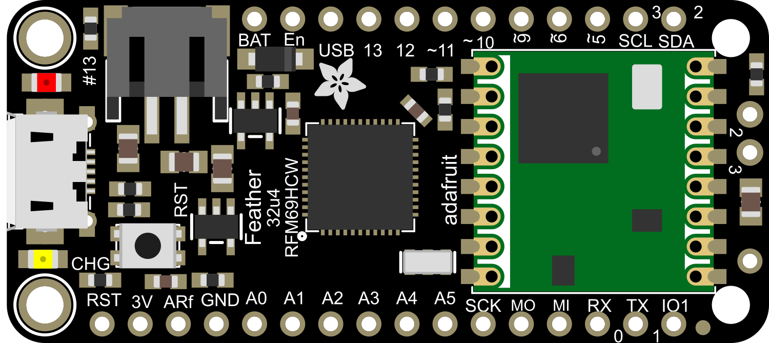
Pin Configuration and Descriptions

Pin Number Function Description
1 GND Ground
2 3V3 3.3V power supply output
3 AREF Analog reference voltage for ADC
4 A0-A5 Analog input pins
5 6-9, 10-13 Digital I/O pins, PWM capable (on some pins)
6 14 (MISO) SPI data input
7 15 (SCK) SPI clock
8 16 (MOSI) SPI data output
9 17 (SS) SPI slave select
10 RX and TX UART receive and transmit
11 SDA and SCL I2C data and clock lines
12 RST Reset pin
13 BAT Battery voltage (for battery-powered applications)
14 USB Micro-USB connection for programming/power
15 RFM9x DIO0-DIO5 Radio module digital I/O pins

Usage Instructions

How to Use the Component in a Circuit

  1. Powering the Board:

    • The Feather 32u4 RFM9x can be powered via the USB connection, a LiPo battery, or through the VIN pin.
    • Ensure that the power source is within the specified voltage range to prevent damage.
  2. Programming:

    • Connect the board to your computer using a micro-USB cable.
    • Select "Adafruit Feather 32u4" from the Tools > Board menu in the Arduino IDE.
    • Choose the correct port from Tools > Port.
  3. Integrating the RFM9x Radio:

    • Use the provided RFM9x DIO pins to interface with the radio module.
    • Ensure that the antenna is properly connected to achieve the maximum range.
  4. Interfacing with Sensors and Actuators:

    • Utilize the digital and analog pins to connect various sensors and actuators.
    • Remember to configure the pins correctly in your code (as input or output).

Important Considerations and Best Practices

  • Antenna: Always use the board with an antenna connected to the RFM9x module to avoid damaging the transmitter.
  • Power Consumption: To achieve low-power operation, utilize sleep modes and minimize the duty cycle of radio transmissions.
  • Interference: Be aware of potential interference in the operating environment, which can affect communication range and reliability.
  • Regulatory Compliance: Ensure that your use of the radio module complies with local regulations regarding radio frequency and power output.

Troubleshooting and FAQs

Common Issues

  • Board not recognized by computer:
    • Check the USB cable and connections.
    • Ensure that the correct drivers are installed.
  • Radio communication not working:
    • Verify that the antenna is properly connected.
    • Check that the frequency and settings match on both the transmitting and receiving devices.
  • Low range or unreliable communication:
    • Ensure there are no obstructions or sources of interference.
    • Consider using a higher gain antenna or adjusting the placement of the device.

Solutions and Tips for Troubleshooting

  • Reset the board: If the board is unresponsive, try pressing the reset button.
  • Update the bootloader: If you have issues uploading sketches, it may be necessary to update the bootloader using an ISP programmer.
  • Check solder joints: If you've soldered headers or components to the board, ensure that all connections are solid and there are no shorts.

FAQs

  • Q: Can I use the Feather 32u4 RFM9x with a different microcontroller?
    • A: Yes, you can communicate with the RFM9x module using SPI, which is available on many microcontrollers.
  • Q: What is the maximum range I can achieve with this board?
    • A: The range can vary greatly depending on the environment, but with line-of-sight and proper settings, you can achieve up to 2 km.
  • Q: Can I use this board with the Arduino IDE?
    • A: Yes, the Feather 32u4 RFM9x is fully compatible with the Arduino IDE.

Example Code for Arduino UNO

Below is a simple example code snippet that demonstrates how to initialize the RFM9x module with an Arduino UNO. This code assumes you have the appropriate library installed (e.g., RadioHead library).

#include <SPI.h>
#include <RH_RF95.h>

// Singleton instance of the radio driver
RH_RF95 rf95;

void setup() {
  Serial.begin(9600);
  while (!Serial) ; // Wait for serial port to be available
  if (!rf95.init())
    Serial.println("init failed");
}

void loop() {
  // Send a message every 3 seconds
  if (rf95.available()) {
    // Should be a message for us now
    uint8_t buf[RH_RF95_MAX_MESSAGE_LEN];
    uint8_t len = sizeof(buf);
    if (rf95.recv(buf, &len)) {
      Serial.print("Got: ");
      Serial.println((char*)buf);
    } else {
      Serial.println("Receive failed");
    }
  }
}

Remember to install the RadioHead library before uploading this code to your Arduino UNO. This example is for demonstration purposes and may require modifications to work with your specific setup.