How to Use Mini AC-DC 110V-230V to 5V 2000mA Module: Examples, Pinouts, and Specs
Introduction
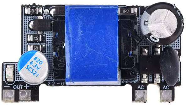
The Mini AC-DC 110V-230V to 5V 2000mA Module is a compact and efficient power supply module designed to convert high AC voltage (110V-230V) into a stable 5V DC output. With a maximum current output of 2000mA, this module is ideal for powering low-voltage electronic devices, microcontrollers, IoT devices, and other small circuits. Its small size and high efficiency make it a popular choice for embedded systems and DIY electronics projects.
Explore Projects Built with Mini AC-DC 110V-230V to 5V 2000mA Module


Explore Projects Built with Mini AC-DC 110V-230V to 5V 2000mA Module
Common Applications and Use Cases
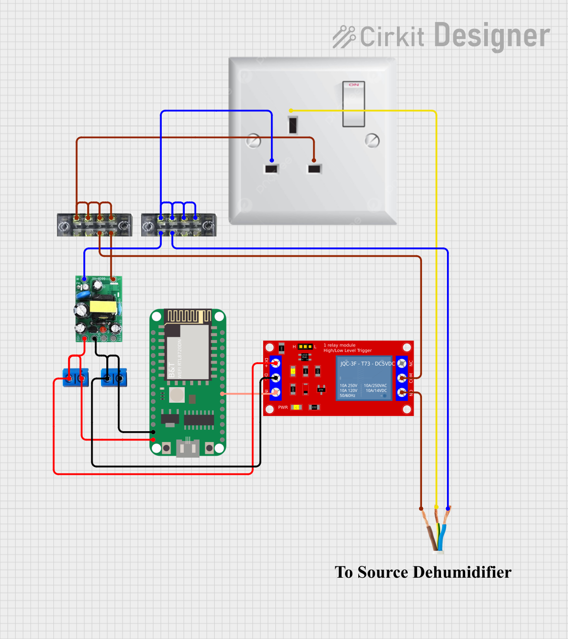
- Powering microcontrollers such as Arduino, ESP8266, or Raspberry Pi Pico.
- Supplying power to IoT devices and sensors.
- Replacing bulky power adapters in compact electronic designs.
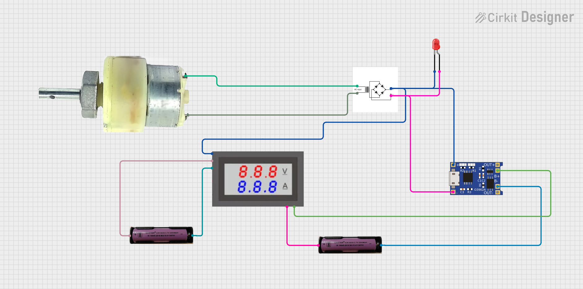
- Providing a stable 5V DC output for LED strips, relays, or small motors.
- Used in home automation systems and smart devices.
Technical Specifications
Key Technical Details
| Parameter | Value |
|---|---|
| Input Voltage Range | 110V AC to 230V AC |
| Output Voltage | 5V DC |
| Maximum Output Current | 2000mA (2A) |
| Power Output | 10W |
| Efficiency | ≥ 80% |
| Operating Temperature | -25°C to +70°C |
| Dimensions | Compact (varies by model) |
| Isolation Voltage | 3000V AC |
| Protection Features | Overload, short circuit, and over-temperature protection |
Pin Configuration and Descriptions
| Pin Name | Description |
|---|---|
| AC IN (L) | Live wire input for AC voltage (110V-230V). |
| AC IN (N) | Neutral wire input for AC voltage (110V-230V). |
| DC OUT (+) | Positive terminal for 5V DC output. |
| DC OUT (-) | Negative terminal (ground) for 5V DC output. |
Usage Instructions
How to Use the Module in a Circuit
- Safety First: Ensure the module is disconnected from any power source before wiring. Handle the module carefully, as it deals with high AC voltages.
- Connect the AC Input:
- Connect the
AC IN (L)pin to the live wire of the AC power source. - Connect the
AC IN (N)pin to the neutral wire of the AC power source. - Use proper insulation and secure connections to avoid electrical hazards.
- Connect the
- Connect the DC Output:
- Connect the
DC OUT (+)pin to the positive terminal of your load or circuit. - Connect the
DC OUT (-)pin to the ground terminal of your load or circuit.
- Connect the
- Power On: Once all connections are secure, supply AC power to the module. The module will convert the AC input to a stable 5V DC output.
Important Considerations and Best Practices
- Isolation: Ensure proper isolation between the AC and DC sides to prevent electrical shocks.
- Heat Dissipation: If the module is used near its maximum current rating (2A), ensure adequate ventilation or heat dissipation to prevent overheating.
- Load Compatibility: Verify that the connected load does not exceed the module's maximum output current (2000mA).
- Testing: Use a multimeter to confirm the output voltage (5V DC) before connecting sensitive devices.
- Mounting: Secure the module in a non-conductive enclosure to protect it from dust, moisture, and accidental contact.
Example: Using the Module with an Arduino UNO
The Mini AC-DC module can be used to power an Arduino UNO directly via its 5V pin. Below is an example of how to connect the module and a simple Arduino sketch to blink an LED.
Wiring Diagram
- Connect the
DC OUT (+)pin of the module to the 5V pin of the Arduino UNO. - Connect the
DC OUT (-)pin of the module to the GND pin of the Arduino UNO. - Connect an LED to pin 13 of the Arduino UNO with a 220-ohm resistor in series.
Arduino Code
// Simple LED Blink Example
// This code blinks an LED connected to pin 13 of the Arduino UNO.

void setup() {
  pinMode(13, OUTPUT); // Set pin 13 as an output pin
}

void loop() {
  digitalWrite(13, HIGH); // Turn the LED on
  delay(1000);            // Wait for 1 second
  digitalWrite(13, LOW);  // Turn the LED off
  delay(1000);            // Wait for 1 second
}
Troubleshooting and FAQs
Common Issues and Solutions
| Issue | Possible Cause | Solution |
|---|---|---|
| No output voltage | Incorrect wiring of AC input | Double-check the AC IN (L) and AC IN (N) connections. |
| Output voltage is unstable | Overloading the module | Ensure the connected load does not exceed 2000mA. |
| Module overheating | Insufficient ventilation or high load | Reduce the load or improve heat dissipation. |
| Arduino or device not powering on | Loose connections or faulty wiring | Verify all connections and ensure proper contact. |
FAQs
Can this module power a Raspberry Pi?
- No, the Raspberry Pi typically requires more than 2A of current, especially with peripherals connected. Use a higher-rated power supply for Raspberry Pi devices.
Is the module safe to use in open circuits?
- No, the module should be enclosed in a non-conductive case to prevent accidental contact with high-voltage components.
Can I use this module outdoors?
- The module is not weatherproof. Use it only in dry, indoor environments or within a weatherproof enclosure.
What happens if the input voltage exceeds 230V AC?
- The module may fail or become damaged. Ensure the input voltage stays within the specified range (110V-230V AC).
By following these guidelines and precautions, you can safely and effectively use the Mini AC-DC 110V-230V to 5V 2000mA Module in your projects.