How to Use MKE-M06-5V-Fet-Module: Examples, Pinouts, and Specs
Introduction
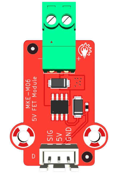
The MKE-M06-5V-Fet-Module is a compact and efficient module designed for controlling high-power loads using MOSFETs. Operating at a standard 5V logic level, this module is ideal for applications requiring precise switching and control of high-current devices. It is commonly used in motor control, LED dimming, heating element regulation, and other high-power switching tasks. Its robust design ensures reliable performance in a variety of environments.
Explore Projects Built with MKE-M06-5V-Fet-Module

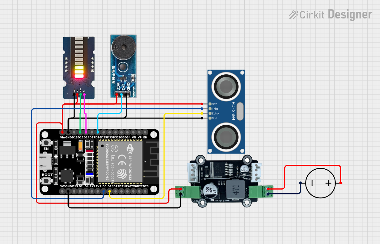

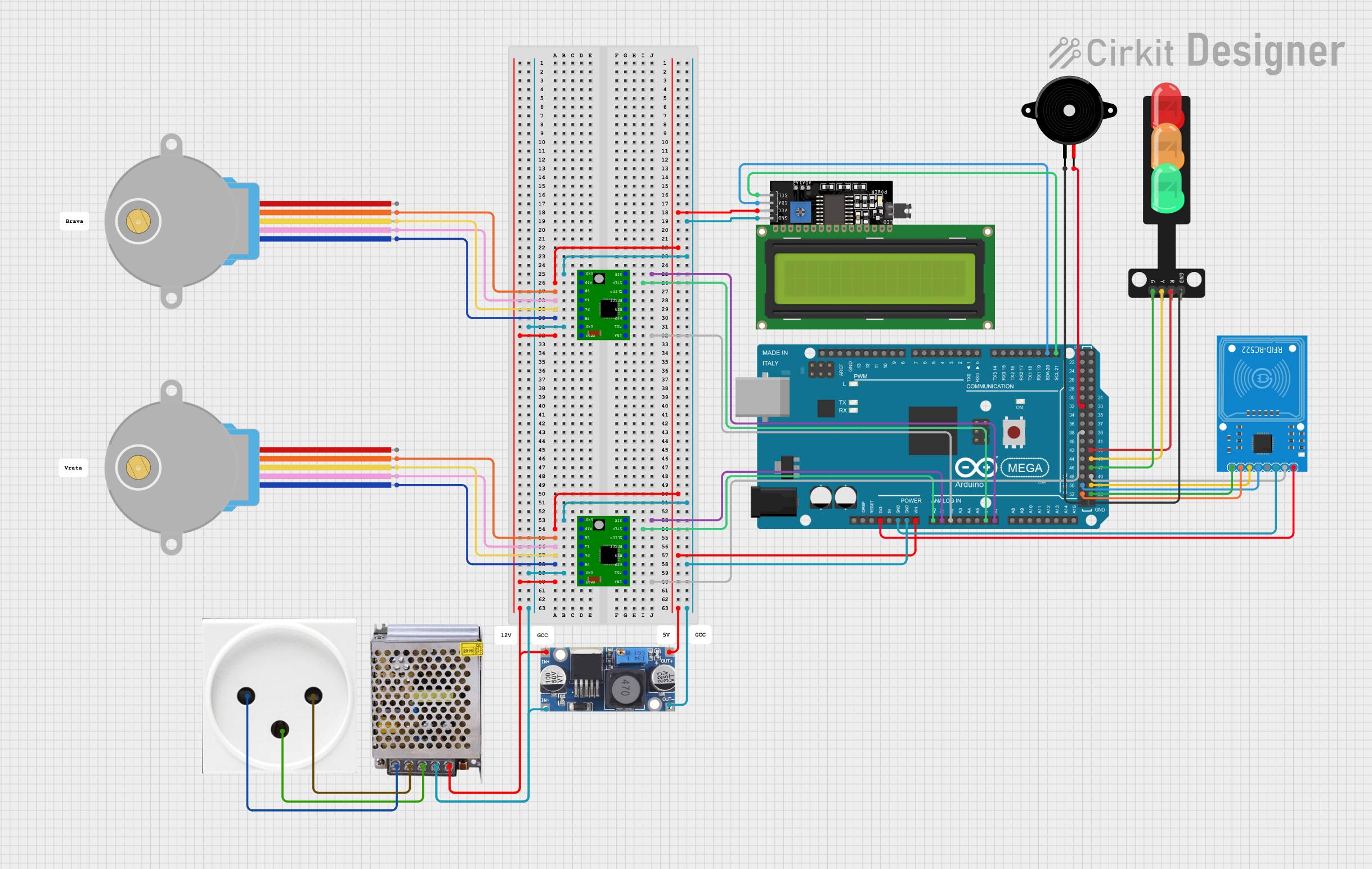
Explore Projects Built with MKE-M06-5V-Fet-Module
Common Applications
- Motor speed control in robotics and automation systems
- LED dimming for lighting applications
- Switching high-power resistive loads such as heating elements
- General-purpose high-current switching in DIY and industrial projects
Technical Specifications
Key Technical Details
| Parameter | Value |
|---|---|
| Operating Voltage | 5V DC |
| Control Signal Voltage | 3.3V to 5V logic level |
| Maximum Load Voltage | 30V DC |
| Maximum Load Current | 10A (with proper heat dissipation) |
| MOSFET Type | N-Channel |
| Module Dimensions | 40mm x 20mm x 10mm |
| Onboard Protection | Flyback diode for inductive loads |
Pin Configuration and Descriptions
| Pin Name | Pin Type | Description |
|---|---|---|
| VCC | Power Input | Connect to 5V DC power supply. |
| GND | Ground | Connect to the ground of the power supply. |
| IN | Signal Input | Control signal input (3.3V or 5V logic level). |
| OUT+ | Load Positive | Connect to the positive terminal of the load. |
| OUT- | Load Negative | Connect to the negative terminal of the load. |
Usage Instructions
How to Use the Component in a Circuit
- Power the Module: Connect the
VCCpin to a 5V DC power supply and theGNDpin to the ground of the same power supply. - Connect the Load: Attach the load (e.g., motor, LED strip) between the
OUT+andOUT-pins. Ensure the load's voltage and current ratings are within the module's specifications. - Control Signal: Use a microcontroller (e.g., Arduino UNO) or other logic-level device to send a control signal to the
INpin. A HIGH signal (3.3V or 5V) will turn the MOSFET on, allowing current to flow through the load. - Heat Dissipation: For high-current loads, ensure proper heat dissipation by attaching a heatsink to the MOSFET or using active cooling.
Important Considerations and Best Practices
- Inductive Loads: The module includes a flyback diode to protect against voltage spikes from inductive loads (e.g., motors). However, ensure the diode's ratings are sufficient for your application.
- Current Limitations: Do not exceed the maximum current rating of 10A. For continuous high-current operation, use additional cooling.
- Signal Voltage: Ensure the control signal voltage matches the module's input range (3.3V to 5V).
- Wiring: Use appropriately rated wires for high-current connections to avoid overheating or voltage drops.
Example: Using with Arduino UNO
Below is an example of how to control an LED strip using the MKE-M06-5V-Fet-Module and an Arduino UNO.
// Example: Controlling an LED strip with MKE-M06-5V-Fet-Module
// Connect the IN pin of the module to Arduino pin 9
// Connect the LED strip to OUT+ and OUT- of the module
// Ensure the module's VCC and GND are connected to a 5V power supply

#define FET_MODULE_PIN 9  // Define the Arduino pin connected to the module's IN pin

void setup() {
  pinMode(FET_MODULE_PIN, OUTPUT);  // Set the pin as an output
}

void loop() {
  digitalWrite(FET_MODULE_PIN, HIGH);  // Turn on the LED strip
  delay(1000);                         // Wait for 1 second
  digitalWrite(FET_MODULE_PIN, LOW);   // Turn off the LED strip
  delay(1000);                         // Wait for 1 second
}
Troubleshooting and FAQs
Common Issues and Solutions
The load does not turn on:
- Ensure the
VCCandGNDpins are properly connected to a 5V power supply. - Verify that the control signal voltage is within the acceptable range (3.3V to 5V).
- Check the wiring of the load to the
OUT+andOUT-pins.
- Ensure the
The MOSFET overheats:
- Ensure the load current does not exceed 10A.
- Attach a heatsink to the MOSFET for high-current applications.
- Verify that the load voltage is within the module's maximum rating (30V DC).
The module does not respond to the control signal:
- Confirm that the control signal is properly connected to the
INpin. - Check the microcontroller's output pin configuration and ensure it is set as an output.
- Test the control signal with a multimeter to verify it is toggling between HIGH and LOW.
- Confirm that the control signal is properly connected to the
FAQs
Q: Can I use this module with a 12V power supply?
A: Yes, the module can control loads up to 30V DC. However, the control signal and module power (VCC) must still be 5V.
Q: Is the module suitable for AC loads?
A: No, the MKE-M06-5V-Fet-Module is designed for DC loads only.
Q: Can I use this module with a Raspberry Pi?
A: Yes, the module is compatible with the Raspberry Pi's 3.3V GPIO logic levels. Ensure proper wiring and signal voltage.
Q: Do I need an external flyback diode for motors?
A: The module includes a built-in flyback diode for basic protection. For high-power motors, consider adding an external diode with higher ratings for additional safety.