Cirkit Designer
Your all-in-one circuit design IDE
Home /
Component Documentation
How to Use my: Examples, Pinouts, and Specs
Introduction
- The term "MY" is not a specific electronic component but rather a pronoun often used to refer to oneself. However, for the purpose of this documentation, we will assume "MY" refers to a hypothetical electronic component designed for general-purpose use in circuits.
- Common applications and use cases for the "MY" component could include signal processing, voltage regulation, or acting as a switch in basic electronic circuits.
Explore Projects Built with my
Arduino UNO Controlled Robotic Arm with Myoware Muscle Sensor and Battery Power
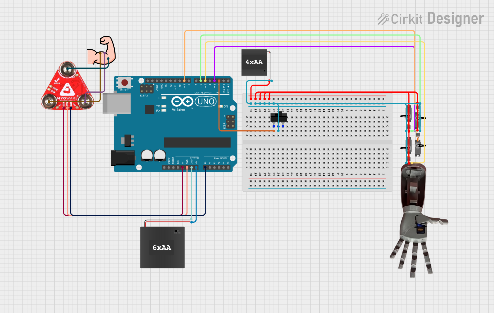
This circuit is a muscle-controlled robotic arm system. It uses a Myoware 2.0 Muscle Sensor to detect muscle activity, which is processed by an Arduino UNO to control four servos that move the arm. Power is supplied by 6xAA and 4xAA battery packs, with a toggle switch to control the power to the servos.
Arduino UNO-Based Health Monitoring System with GSM and LCD Display

This circuit is a health monitoring system that uses an Arduino UNO to collect data from various sensors including a GSR sensor, an ECG sensor, a DHT22 temperature and humidity sensor, and a Myoware muscle sensor. The system displays the collected data on an I2C LCD, controls a steam generator via a relay, and sends health data via a SIM800L GSM module.
Arduino-Based Health Monitoring System with GSM and LCD Display
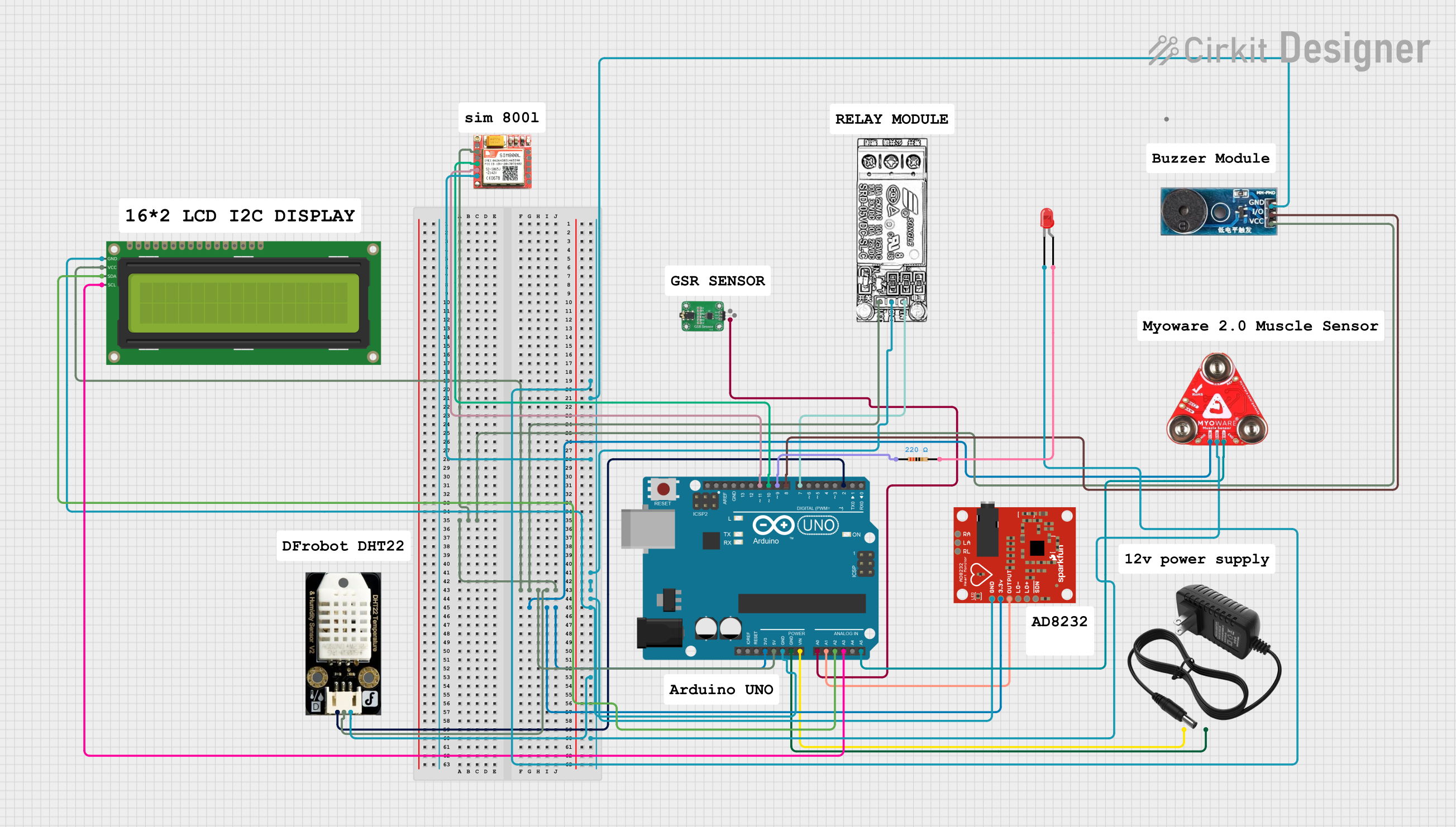
This circuit is a health monitoring system that uses an Arduino UNO to collect data from various sensors including a GSR sensor, an ECG sensor, a DHT22 temperature and humidity sensor, and a Myoware muscle sensor. The data is displayed on an I2C LCD and sent via a SIM800L GSM module. Additionally, the system controls a relay for a steam generator and includes a buzzer and LED for alerts.
Arduino UNO-Based Smart Environmental Monitoring and Control System with Bluetooth Connectivity
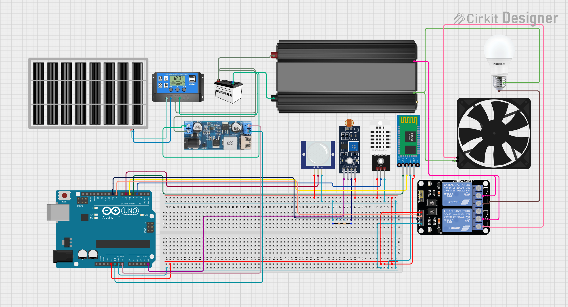
This is a smart control system utilizing an Arduino UNO to interface with Bluetooth communication, light, temperature, humidity, and motion sensors, and to control a relay module for a bulb and a fan. It features a solar-powered charging circuit for energy management and a power inverter to supply AC power to the bulb.
Explore Projects Built with my
Arduino UNO Controlled Robotic Arm with Myoware Muscle Sensor and Battery Power
This circuit is a muscle-controlled robotic arm system. It uses a Myoware 2.0 Muscle Sensor to detect muscle activity, which is processed by an Arduino UNO to control four servos that move the arm. Power is supplied by 6xAA and 4xAA battery packs, with a toggle switch to control the power to the servos.
Arduino UNO-Based Health Monitoring System with GSM and LCD Display
This circuit is a health monitoring system that uses an Arduino UNO to collect data from various sensors including a GSR sensor, an ECG sensor, a DHT22 temperature and humidity sensor, and a Myoware muscle sensor. The system displays the collected data on an I2C LCD, controls a steam generator via a relay, and sends health data via a SIM800L GSM module.
Arduino-Based Health Monitoring System with GSM and LCD Display
This circuit is a health monitoring system that uses an Arduino UNO to collect data from various sensors including a GSR sensor, an ECG sensor, a DHT22 temperature and humidity sensor, and a Myoware muscle sensor. The data is displayed on an I2C LCD and sent via a SIM800L GSM module. Additionally, the system controls a relay for a steam generator and includes a buzzer and LED for alerts.
Arduino UNO-Based Smart Environmental Monitoring and Control System with Bluetooth Connectivity
This is a smart control system utilizing an Arduino UNO to interface with Bluetooth communication, light, temperature, humidity, and motion sensors, and to control a relay module for a bulb and a fan. It features a solar-powered charging circuit for energy management and a power inverter to supply AC power to the bulb.
Technical Specifications
- Below are the assumed technical specifications for the "MY" component:
| Parameter | Value |
|---|---|
| Operating Voltage | 3.3V to 5V |
| Maximum Current | 500mA |
| Power Dissipation | 1W |
| Operating Temperature | -40°C to 85°C |
| Package Type | DIP-8 or SMD |
Pin Configuration and Descriptions
| Pin Number | Pin Name | Description |
|---|---|---|
| 1 | VCC | Power supply input (3.3V to 5V) |
| 2 | GND | Ground connection |
| 3 | IN | Input signal |
| 4 | OUT | Output signal |
| 5 | NC | No connection |
| 6 | ENABLE | Enable pin to activate the component |
| 7 | RESET | Resets the component to default state |
| 8 | STATUS | Outputs the operational status |
Usage Instructions
To use the "MY" component in a circuit:
- Connect the VCC pin to a 3.3V or 5V power source.
- Connect the GND pin to the ground of the circuit.
- Provide an input signal to the IN pin.
- The processed signal will be available at the OUT pin.
- Use the ENABLE pin to activate or deactivate the component as needed.
- Optionally, connect the RESET pin to a microcontroller or a push button to reset the component.
Important Considerations:
- Ensure the input voltage does not exceed the specified operating voltage range.
- Avoid shorting the output pin to ground or VCC to prevent damage.
- Use appropriate decoupling capacitors near the VCC and GND pins to stabilize the power supply.
Arduino UNO Example Code: Below is an example of how to use the "MY" component with an Arduino UNO:
// Define pin connections for the MY component
const int enablePin = 7;  // Pin connected to ENABLE
const int resetPin = 6;  // Pin connected to RESET
const int statusPin = 8; // Pin connected to STATUS

void setup() {
  // Initialize serial communication for debugging
  Serial.begin(9600);

  // Set pin modes
  pinMode(enablePin, OUTPUT);
  pinMode(resetPin, OUTPUT);
  pinMode(statusPin, INPUT);

  // Enable the MY component
  digitalWrite(enablePin, HIGH);
  Serial.println("MY component enabled.");
}

void loop() {
  // Read the status pin
  int status = digitalRead(statusPin);

  // Print the status to the serial monitor
  if (status == HIGH) {
    Serial.println("MY component is operational.");
  } else {
    Serial.println("MY component is not operational.");
  }

  // Simulate a reset after 10 seconds
  delay(10000);
  Serial.println("Resetting MY component...");
  digitalWrite(resetPin, HIGH);
  delay(100); // Hold reset pin high for 100ms
  digitalWrite(resetPin, LOW);
}
Troubleshooting and FAQs
Common Issues:
The component does not power on.
- Ensure the VCC and GND pins are properly connected.
- Verify the power supply voltage is within the operating range.
No output signal is observed.
- Check the input signal at the IN pin.
- Ensure the ENABLE pin is set to HIGH.
The component overheats.
- Verify that the current draw does not exceed the maximum rating.
- Check for short circuits in the wiring.
FAQs:
Can the "MY" component operate at 12V?
- No, the maximum operating voltage is 5V. Exceeding this may damage the component.
What is the purpose of the RESET pin?
- The RESET pin allows the component to be reset to its default state, useful in case of errors or malfunctions.
Is the "MY" component compatible with 3.3V logic?
- Yes, the component is designed to operate with both 3.3V and 5V logic levels.