How to Use DIP Switch 1 Position: Examples, Pinouts, and Specs

Introduction
A DIP (Dual Inline Package) Switch 1 Position is a simple, manual electrical switch used in electronic circuits. It is designed to offer a single binary choice to the user, allowing for the control of electrical signals with an ON or OFF position. This type of switch is often utilized in settings where a single configuration option or mode selection is required, such as selecting between two voltage levels or toggling a feature on or off.
Explore Projects Built with DIP Switch 1 Position
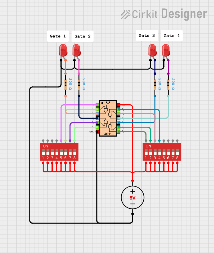
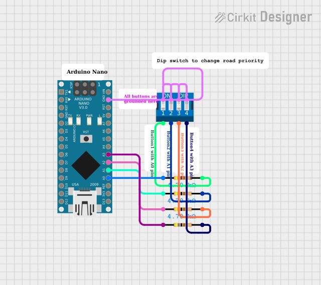


Explore Projects Built with DIP Switch 1 Position
Common Applications and Use Cases
- Configuration settings on electronic devices
- Selecting operating modes in circuits
- Setting hardware addresses for networked devices
- Enabling or disabling features in electronic toys and gadgets
Technical Specifications
Key Technical Details
- Voltage Rating: Typically 3.3V to 5V
- Current Rating: Usually around 25mA
- Contact Resistance: Maximum 100mΩ initial
- Insulation Resistance: Minimum 100MΩ at 500V DC
- Dielectric Strength: Typically 500V AC for 1 minute
- Operating Temperature: -40°C to +85°C
Pin Configuration and Descriptions
| Pin Number | Description |
|---|---|
| 1 | Common terminal |
| 2 | Normally open (NO) contact |
Usage Instructions
How to Use the Component in a Circuit
- Mounting: Insert the DIP switch into the designated place on the PCB, ensuring correct orientation.
- Connection: Connect the common terminal (pin 1) to the circuit node where the switch control is required.
- Operation: Toggle the switch to the ON position to close the circuit or to the OFF position to open the circuit.
Important Considerations and Best Practices
- Voltage and Current: Do not exceed the voltage and current ratings of the switch to avoid damage.
- Debouncing: Although not as prone to bouncing as mechanical buttons, consider implementing a debounce circuit or software debouncing if precise control is necessary.
- Cleaning: Avoid using aggressive cleaning agents that could damage the switch components or its plastic body.
Example Code for Arduino UNO
// Define the pin connected to the DIP switch
const int dipSwitchPin = 2;

void setup() {
  // Set the DIP switch pin as input
  pinMode(dipSwitchPin, INPUT);
  // Initialize serial communication at 9600 bits per second
  Serial.begin(9600);
}

void loop() {
  // Read the state of the DIP switch
  int switchState = digitalRead(dipSwitchPin);

  // Print the state of the DIP switch to the Serial Monitor
  Serial.print("DIP Switch State: ");
  if (switchState == HIGH) {
    Serial.println("ON");
  } else {
    Serial.println("OFF");
  }

  // Wait for a bit to avoid spamming the Serial Monitor
  delay(500);
}
Troubleshooting and FAQs
Common Issues Users Might Face
- Switch Does Not Change State: Ensure the switch is properly mounted and soldered onto the PCB.
- Inconsistent Readings: Check for loose connections or potential short circuits near the switch terminals.
Solutions and Tips for Troubleshooting
- Visual Inspection: Look for any signs of physical damage or improper installation.
- Continuity Test: Use a multimeter to check for continuity when the switch is in the ON position.
- Debounce: If the switch state appears to fluctuate rapidly, implement a debounce mechanism.
FAQs
Q: Can I use the DIP switch with higher voltages? A: No, you should adhere to the specified voltage rating to prevent damage to the switch.
Q: Is it necessary to power off the circuit before changing the switch position? A: While it is generally safe to toggle the switch with the circuit powered, it is good practice to power down when making changes to avoid any unintended consequences.
Q: How do I know if the switch is in the ON or OFF position? A: The ON position typically aligns the switch actuator with the labeled ON marking on the switch body. You can also use a multimeter to confirm the state.