How to Use ECG Modulo AD8232 ECG: Examples, Pinouts, and Specs
Introduction
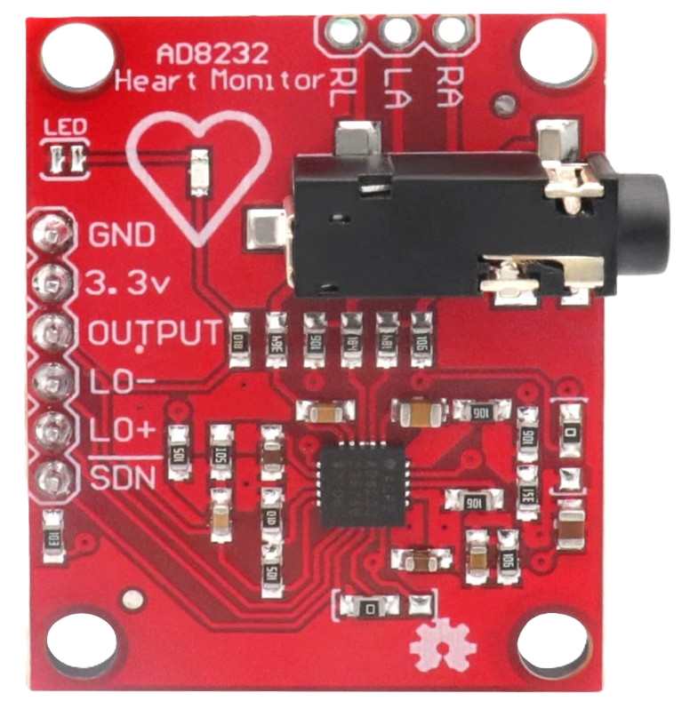
The AD8232 ECG module, manufactured by ICQUANZX, is a compact and efficient solution for acquiring and processing electrocardiogram (ECG) signals. It is built around the AD8232 chip, a low-power, high-performance instrumentation amplifier designed specifically for bioelectric signal conditioning. This module is ideal for applications requiring real-time heart rate monitoring, such as wearable health devices, fitness trackers, and medical diagnostics.
Explore Projects Built with ECG Modulo AD8232 ECG
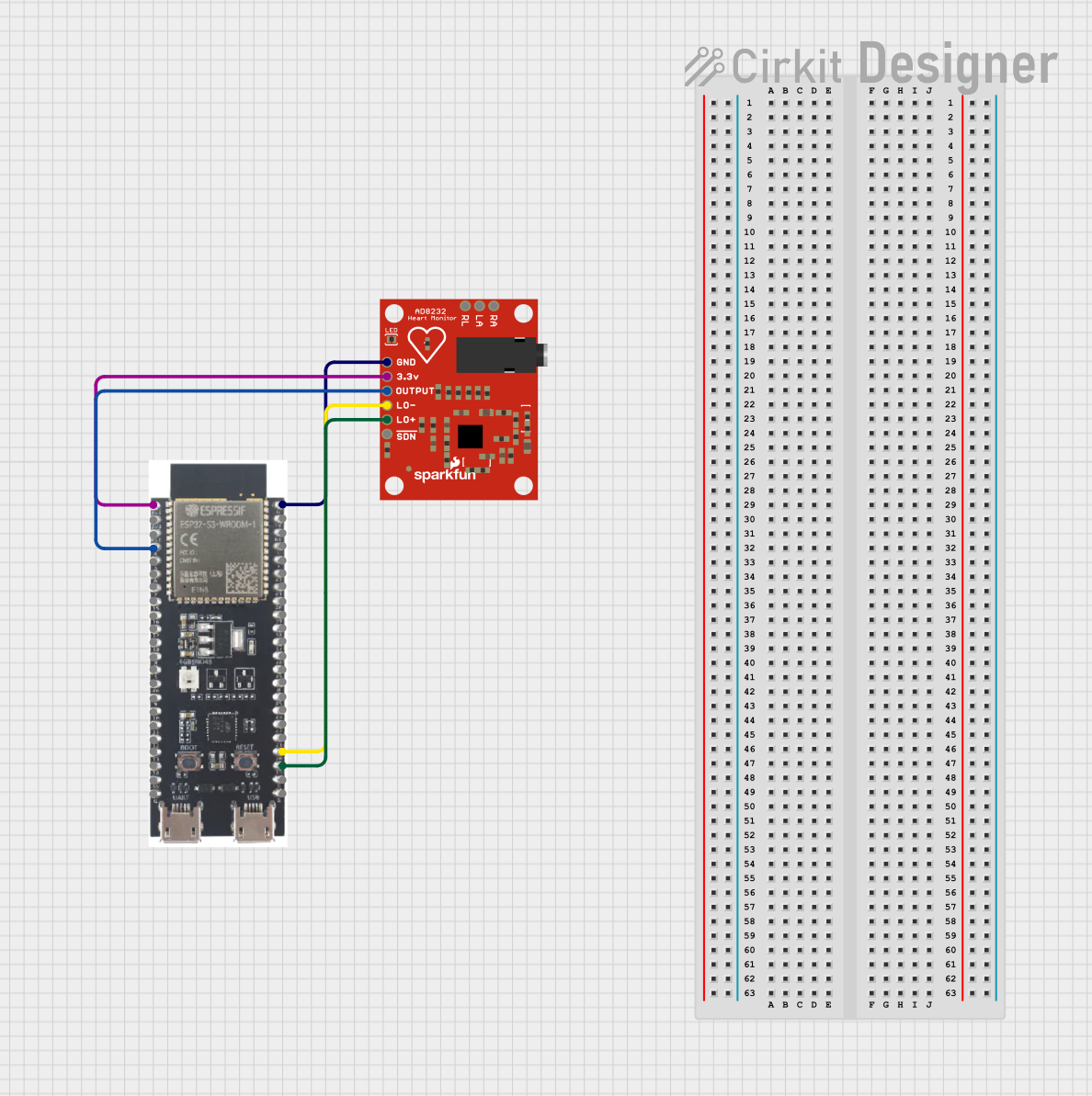
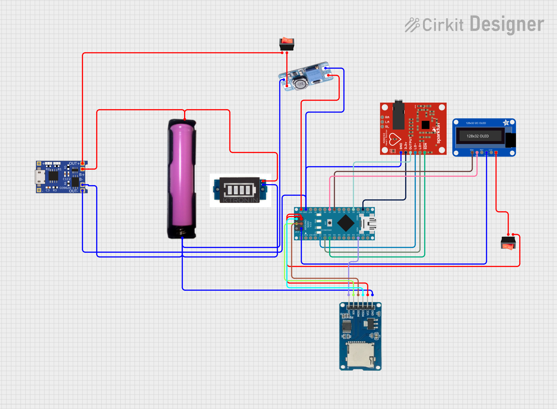
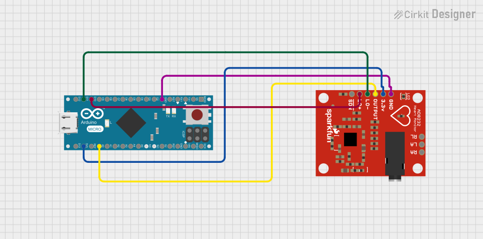
Explore Projects Built with ECG Modulo AD8232 ECG
Common Applications
- Wearable health monitoring systems
- Fitness trackers
- Medical diagnostics and research
- Heart rate monitoring in IoT devices
- Educational and prototyping projects
Technical Specifications
The AD8232 ECG module is designed to provide reliable and accurate ECG signal acquisition. Below are its key technical details:
Key Specifications
| Parameter | Value |
|---|---|
| Operating Voltage | 3.3V to 6V |
| Operating Current | ~170 µA |
| Output Signal | Analog (0-3.3V typical) |
| Gain | Programmable (default ~100) |
| Bandwidth | 0.5 Hz to 40 Hz |
| Input Impedance | >10 GΩ |
| Dimensions | 35mm x 22mm |
Pin Configuration
The AD8232 ECG module has a simple pinout for easy integration into circuits. Below is the pin configuration:
| Pin Name | Description |
|---|---|
| GND | Ground connection |
| 3.3V | Power supply input (3.3V to 6V) |
| OUTPUT | Analog output signal representing the ECG waveform |
| LO+ | Leads-off detection positive signal (active HIGH when electrode is detached) |
| LO- | Leads-off detection negative signal (active HIGH when electrode is detached) |
| SDN | Shutdown pin (active LOW to disable the module) |
Usage Instructions
The AD8232 ECG module is straightforward to use in a circuit. Below are the steps and best practices for integrating it into your project:
Connecting the Module
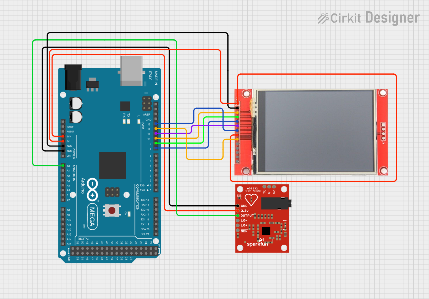
- Power Supply: Connect the
3.3Vpin to a 3.3V or 5V power source and theGNDpin to ground. - Signal Output: Connect the
OUTPUTpin to an analog input pin of a microcontroller (e.g., Arduino UNO) or an oscilloscope for signal visualization. - Electrodes: Attach the three electrodes (RA, LA, RL) to the patient or subject as follows:
- RA (Right Arm): Connect to the right arm.
- LA (Left Arm): Connect to the left arm.
- RL (Right Leg): Connect to the right leg (ground reference).
- Leads-Off Detection: Use the
LO+andLO-pins to monitor electrode detachment. These pins output HIGH when the corresponding electrode is disconnected.
Arduino UNO Example Code
Below is an example of how to use the AD8232 ECG module with an Arduino UNO to read and display ECG signals:
// AD8232 ECG Module Example Code
// This code reads the analog ECG signal from the AD8232 module and displays it
// on the Serial Monitor. Ensure the module is properly connected to the Arduino.

const int ecgPin = A0; // Analog pin connected to the OUTPUT pin of AD8232

void setup() {
  Serial.begin(9600); // Initialize serial communication at 9600 baud
  pinMode(ecgPin, INPUT); // Set the ECG pin as input
}

void loop() {
  int ecgValue = analogRead(ecgPin); // Read the analog ECG signal
  Serial.println(ecgValue); // Print the ECG value to the Serial Monitor
  delay(1); // Small delay for stable readings
}
Best Practices
- Ensure proper placement of electrodes for accurate signal acquisition.
- Avoid excessive movement or interference during signal measurement.
- Use shielded cables for the electrodes to minimize noise.
- If using a battery, ensure it provides a stable voltage within the module's operating range.
Troubleshooting and FAQs
Common Issues and Solutions
| Issue | Possible Cause | Solution |
|---|---|---|
| No output signal | Incorrect wiring or loose connections | Verify all connections and ensure proper power supply. |
| High noise in the signal | Electrode placement or interference | Reposition electrodes and use shielded cables. |
| Leads-off detection always HIGH | Electrodes not properly attached | Ensure electrodes are securely attached to the subject. |
| Output signal is flat or unresponsive | Faulty module or incorrect gain setting | Check the module and verify the gain configuration. |
FAQs
Can I use the AD8232 module with a 5V microcontroller?
- Yes, the module supports a power supply range of 3.3V to 6V, making it compatible with 5V microcontrollers like Arduino UNO.
How do I visualize the ECG waveform?
- You can use the Arduino Serial Plotter or connect the
OUTPUTpin to an oscilloscope for real-time waveform visualization.
- You can use the Arduino Serial Plotter or connect the
What is the purpose of the
SDNpin?- The
SDNpin is used to shut down the module to save power. Pull it LOW to disable the module.
- The
Can I use this module for medical-grade applications?
- The AD8232 module is intended for educational and prototyping purposes. It is not certified for medical-grade applications.
By following this documentation, you can effectively integrate and use the AD8232 ECG module in your projects.