
How to Use Rocker Switch: Examples, Pinouts, and Specs
 Design with Rocker Switch in Cirkit Designer
Introduction
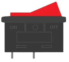
A rocker switch is a type of electrical switch that toggles between two positions, typically used to control power to a device. It features a rectangular or oval shape that rocks back and forth to open or close the circuit. Rocker switches are widely used due to their simplicity, durability, and ease of operation.
Explore Projects Built with Rocker Switch
 Open Project in Cirkit Designer
 Open Project in Cirkit Designer
 Open Project in Cirkit Designer
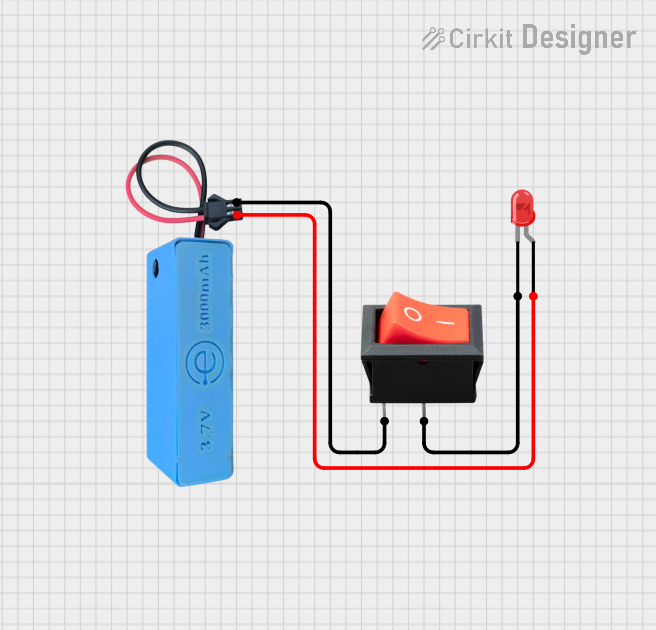 Open Project in Cirkit Designer
Explore Projects Built with Rocker Switch
Open Project in Cirkit DesignerOpen Project in Cirkit DesignerOpen Project in Cirkit DesignerOpen Project in Cirkit DesignerCommon Applications and Use Cases
- Power control for household appliances (e.g., lamps, fans, and heaters)
- Automotive applications (e.g., dashboard controls)
- Industrial equipment and machinery
- Audio and video equipment
- DIY electronics projects
Technical Specifications
Below are the general technical specifications for a standard rocker switch. Note that specific values may vary depending on the manufacturer and model.
| Parameter | Specification |
|---|---|
| Voltage Rating | 12V DC, 24V DC, or 120V/240V AC |
| Current Rating | 5A, 10A, or 15A (depending on model) |
| Contact Resistance | ≤ 50 mΩ |
| Insulation Resistance | ≥ 100 MΩ |
| Operating Temperature | -25°C to +85°C |
| Mechanical Lifespan | 10,000 to 50,000 cycles |
| Mounting Style | Panel mount |
Pin Configuration and Descriptions
Rocker switches typically have two or three pins, depending on whether they are single-pole single-throw (SPST) or single-pole double-throw (SPDT). Below is a table describing the pin configuration:
SPST Rocker Switch
| Pin | Description |
|---|---|
| Pin 1 | Input (connect to power source) |
| Pin 2 | Output (connect to load/device) |
SPDT Rocker Switch
| Pin | Description |
|---|---|
| Pin 1 | Common (connect to power source) |
| Pin 2 | Normally Open (NO) output |
| Pin 3 | Normally Closed (NC) output |
Usage Instructions
How to Use the Component in a Circuit
- Identify the Type of Rocker Switch: Determine whether the switch is SPST or SPDT based on the number of pins and your circuit requirements.
- Connect the Pins:
- For an SPST switch:
- Connect Pin 1 to the positive terminal of the power source.
- Connect Pin 2 to the load (e.g., a light bulb or motor).
- For an SPDT switch:
- Connect Pin 1 (Common) to the positive terminal of the power source.
- Connect Pin 2 (NO) to the load if you want the circuit to be closed when the switch is in the "ON" position.
- Connect Pin 3 (NC) to the load if you want the circuit to be closed when the switch is in the "OFF" position.
- For an SPST switch:
- Secure the Switch: Mount the rocker switch into the panel or enclosure using the provided mounting clips or screws.
- Test the Circuit: Toggle the switch to ensure it operates as expected.
Important Considerations and Best Practices
- Voltage and Current Ratings: Ensure the switch's voltage and current ratings match or exceed the requirements of your circuit.
- Polarity: Rocker switches are generally non-polarized, but always verify the pin configuration before connecting.
- Debouncing: If using the switch in a digital circuit, consider implementing debouncing to avoid erratic behavior.
- Safety: Disconnect power before wiring the switch to prevent electrical shock or damage.
Example: Connecting a Rocker Switch to an Arduino UNO
Below is an example of how to use an SPST rocker switch to control an LED with an Arduino UNO:
// Define pin connections
const int switchPin = 2;  // Pin connected to the rocker switch
const int ledPin = 13;    // Pin connected to the LED

void setup() {
  pinMode(switchPin, INPUT_PULLUP); // Set switch pin as input with pull-up resistor
  pinMode(ledPin, OUTPUT);          // Set LED pin as output
}

void loop() {
  int switchState = digitalRead(switchPin); // Read the state of the switch

  if (switchState == LOW) { // If the switch is pressed (LOW due to pull-up)
    digitalWrite(ledPin, HIGH); // Turn on the LED
  } else {
    digitalWrite(ledPin, LOW);  // Turn off the LED
  }
}
Note: The
INPUT_PULLUPmode is used to simplify the circuit by eliminating the need for an external pull-up resistor.
Troubleshooting and FAQs
Common Issues Users Might Face
Switch Does Not Toggle the Circuit:
- Cause: Incorrect wiring or loose connections.
- Solution: Double-check the pin configuration and ensure all connections are secure.
Switch Feels Stiff or Does Not Rock Smoothly:
- Cause: Mechanical wear or debris inside the switch.
- Solution: Clean the switch or replace it if necessary.
Circuit Overheats or Fails:
- Cause: Exceeding the switch's voltage or current rating.
- Solution: Use a switch with appropriate ratings for your circuit.
LED or Load Does Not Respond:
- Cause: Faulty switch or incorrect Arduino code.
- Solution: Test the switch with a multimeter and verify the code logic.
Solutions and Tips for Troubleshooting
- Use a multimeter to check continuity between the pins when the switch is toggled.
- Ensure the power supply is functioning correctly and providing the required voltage.
- If using the switch with an Arduino, verify that the pinMode and digitalRead/digitalWrite functions are correctly implemented.
By following this documentation, you can effectively integrate a rocker switch into your projects and troubleshoot any issues that arise.