How to Use water flow sensor: Examples, Pinouts, and Specs
Introduction
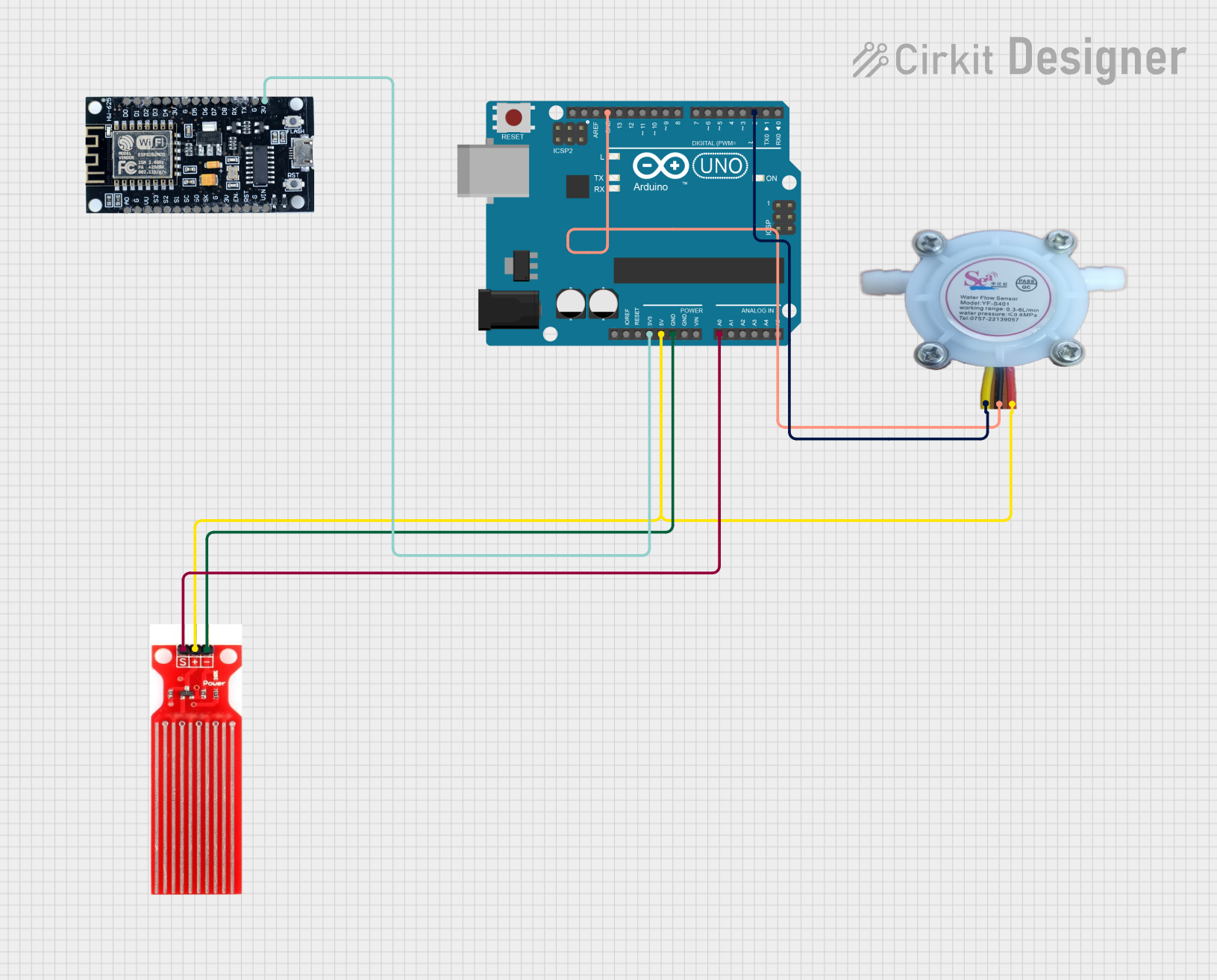
A water flow sensor is an electronic device that measures the flow rate of water through a pipe or conduit. It typically consists of a flow meter, a sensor that can detect the flow of water, and an output signal that can be read by a microcontroller or other data acquisition system. These sensors are commonly used in irrigation systems, water purification systems, and various fluid monitoring applications.
Explore Projects Built with water flow sensor
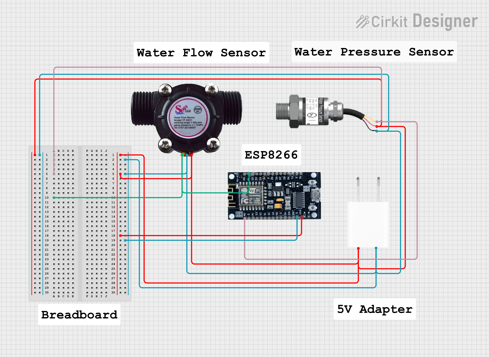
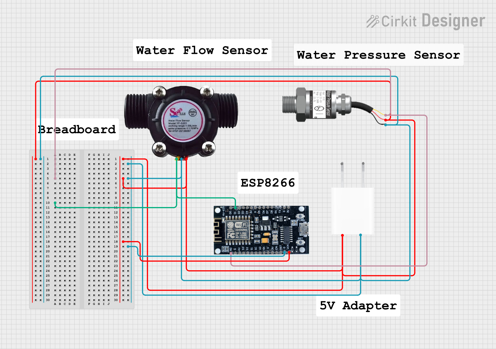
Explore Projects Built with water flow sensor
Common Applications and Use Cases
- Monitoring water usage in residential or commercial buildings
- Irrigation control in agricultural settings
- Industrial flow measurement for process control
- Cooling systems for electronics or machinery
Technical Specifications
Key Technical Details
- Voltage: 5V to 24V DC
- Current: 15 mA (typical)
- Flow Rate Range: 1-30 L/min
- Operating Temperature Range: -25°C to +80°C
- Output Type: Pulse frequency output, proportional to flow rate
Pin Configuration and Descriptions
| Pin Number | Description | Notes |
|---|---|---|
| 1 | GND | Ground connection |
| 2 | VCC | Power supply (5V to 24V DC) |
| 3 | Signal Output | Outputs pulse signal |
Usage Instructions
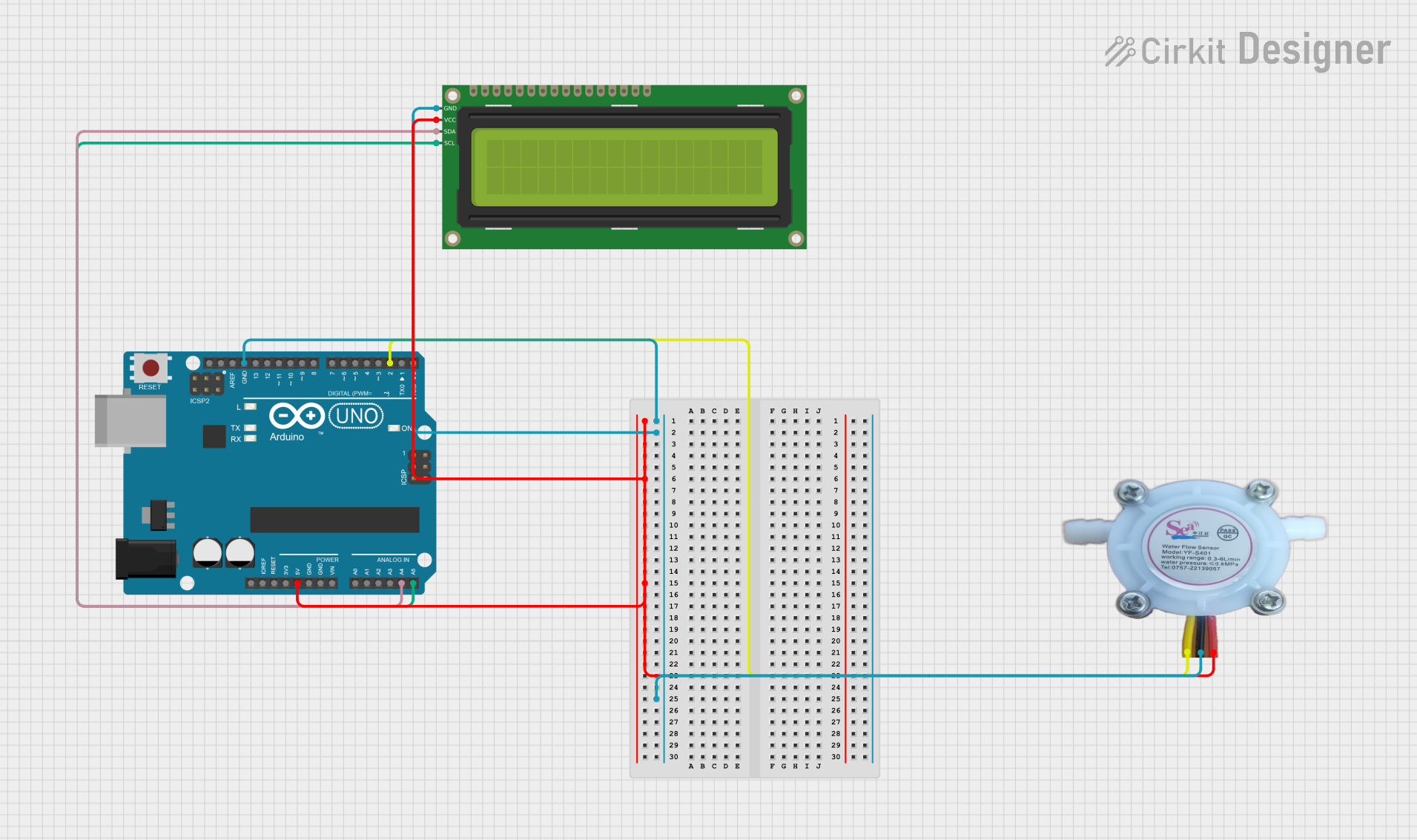
How to Use the Component in a Circuit
- Power Supply: Connect the VCC pin to a power supply within the specified voltage range and the GND pin to the ground of the power supply.
- Signal Output: Connect the signal output pin to a digital input pin on a microcontroller, such as an Arduino UNO, to read the pulse frequency output.
- Flow Measurement: The sensor outputs a series of pulses as water flows through it. The frequency of these pulses is proportional to the flow rate.
Important Considerations and Best Practices
- Ensure that the water flow sensor is installed in the correct orientation as indicated by the arrow on the sensor body.
- Avoid subjecting the sensor to water temperatures outside the specified operating range.
- Use a pull-up resistor if the microcontroller input pin requires one for proper signal reading.
- Apply proper filtering or debouncing techniques to the signal to ensure accurate readings.
Example Code for Arduino UNO
const int flowPin = 2; // The pin connected to the water flow sensor's output
volatile int flowPulseCount; // Measures pulse count from the sensor

void setup() {
  Serial.begin(9600);
  pinMode(flowPin, INPUT);
  attachInterrupt(digitalPinToInterrupt(flowPin), pulseCounter, RISING); // Increment on rising edge of pulse
}

void loop() {
  flowPulseCount = 0; // Reset pulse count
  interrupts(); // Enable interrupts
  delay(1000); // Wait 1 second
  noInterrupts(); // Disable interrupts

  // Calculate the flow rate in L/min
  // (Pulse frequency (Hz) / 7.5 Q) where Q is the flow rate in L/min
  float flowRate = (flowPulseCount / 7.5);
  Serial.print("Flow rate: ");
  Serial.print(flowRate);
  Serial.println(" L/min");
}

// Interrupt service routine
void pulseCounter() {
  // Increment the pulse counter
  flowPulseCount++;
}
Note: The example code assumes a specific calibration factor (7.5) which may vary based on the sensor model. Refer to the sensor's datasheet for the exact calibration factor.
Troubleshooting and FAQs
Common Issues
- Inaccurate Readings: Ensure the sensor is installed correctly and there are no air bubbles in the line.
- No Output Signal: Check the wiring and connections, and ensure the power supply is within the specified range.
- Erratic Readings: Implement software debouncing or use a hardware filter to stabilize the signal.
Solutions and Tips for Troubleshooting
- Calibration: Use a known volume of water to calibrate the sensor for more accurate readings.
- Signal Filtering: Apply a low-pass filter to the signal to reduce noise and improve measurement accuracy.
- Regular Maintenance: Clean the sensor periodically to prevent debris from affecting the flow measurement.
FAQs
Q: Can the water flow sensor be used with hot water? A: It depends on the sensor's operating temperature range. Check the technical specifications for the maximum temperature.
Q: How do I know if the sensor is functioning correctly? A: Test the sensor by measuring a known flow rate and compare it to the sensor's output.
Q: Can the sensor measure flow in both directions? A: No, water flow sensors are typically unidirectional and have an arrow indicating the correct flow direction.
Q: Is it necessary to use an external pull-up resistor? A: Some microcontrollers have internal pull-up resistors that can be enabled via software. If not, an external pull-up resistor may be required.
This documentation provides a comprehensive guide to using a water flow sensor with an Arduino UNO. For further assistance, consult the sensor's datasheet or contact technical support.