How to Use Integrated Step Driver: Examples, Pinouts, and Specs
Introduction
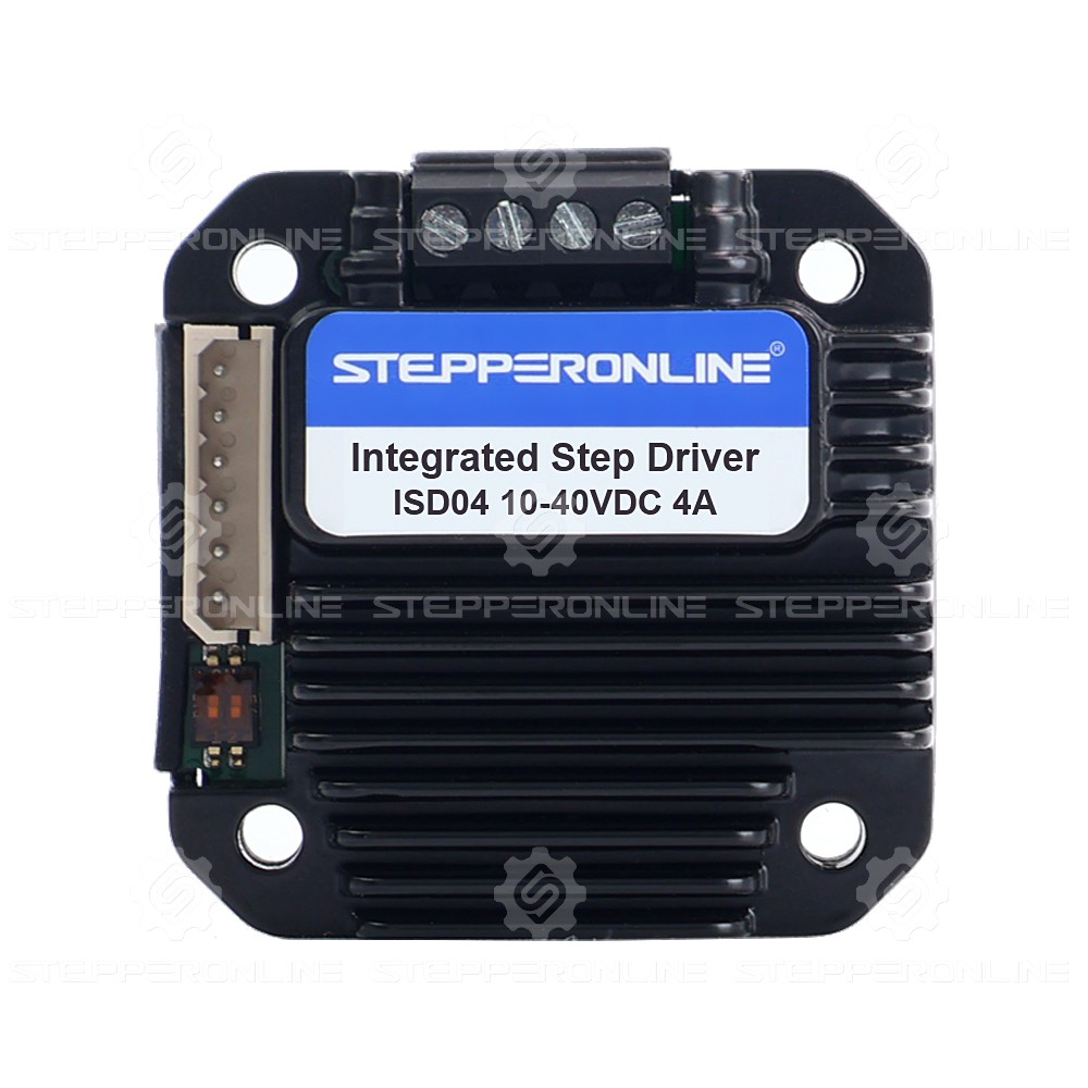
The Integrated Step Driver (ISD04 10-40VDC 4A), manufactured by STEPPERONLINE, is a compact and efficient device designed to control stepper motors. It integrates a stepper motor driver and controller into a single unit, simplifying the design and reducing the space required in motor control systems. This driver provides precise control of the motor's phases, enabling accurate positioning and speed control.
Explore Projects Built with Integrated Step Driver
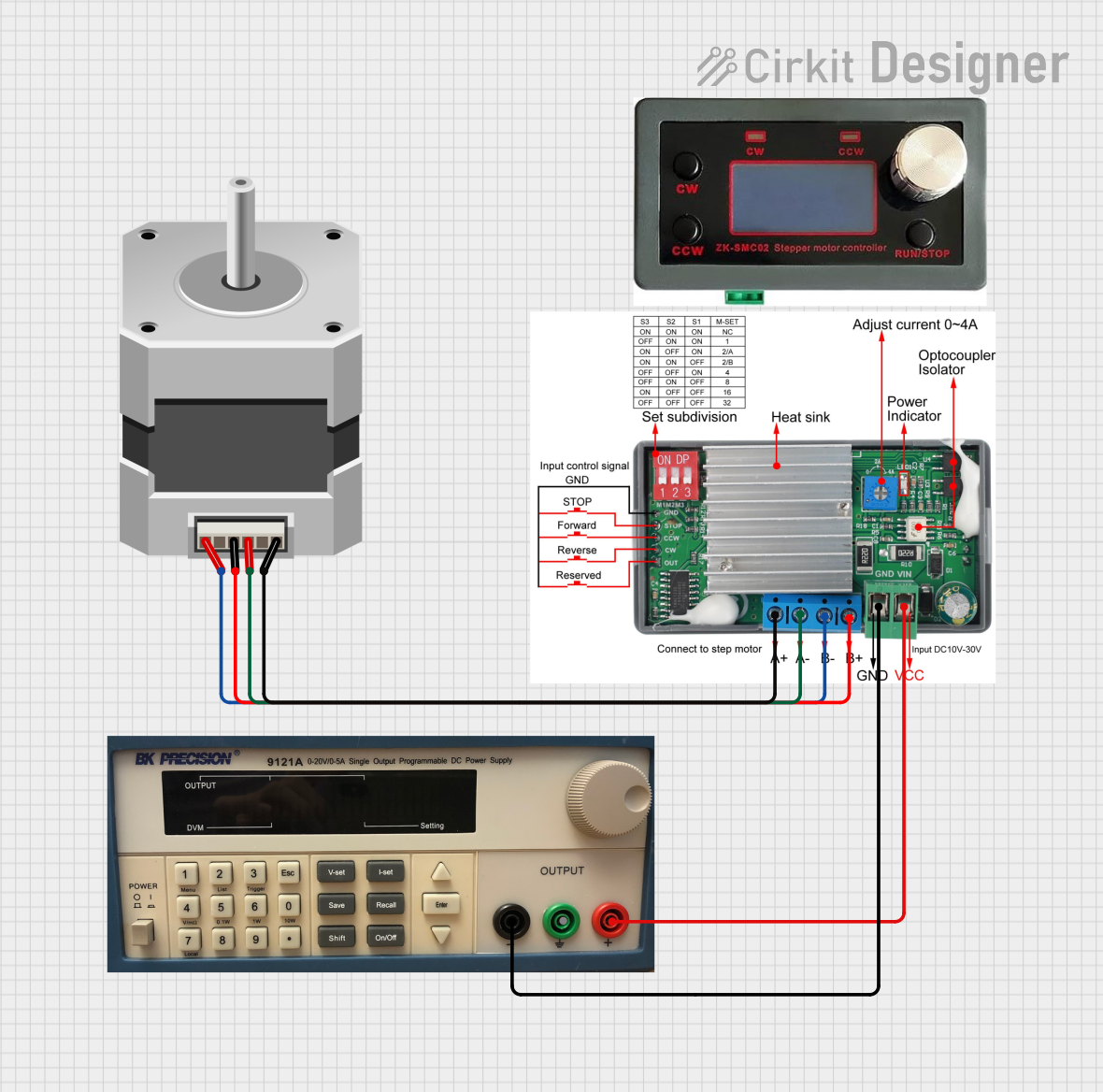
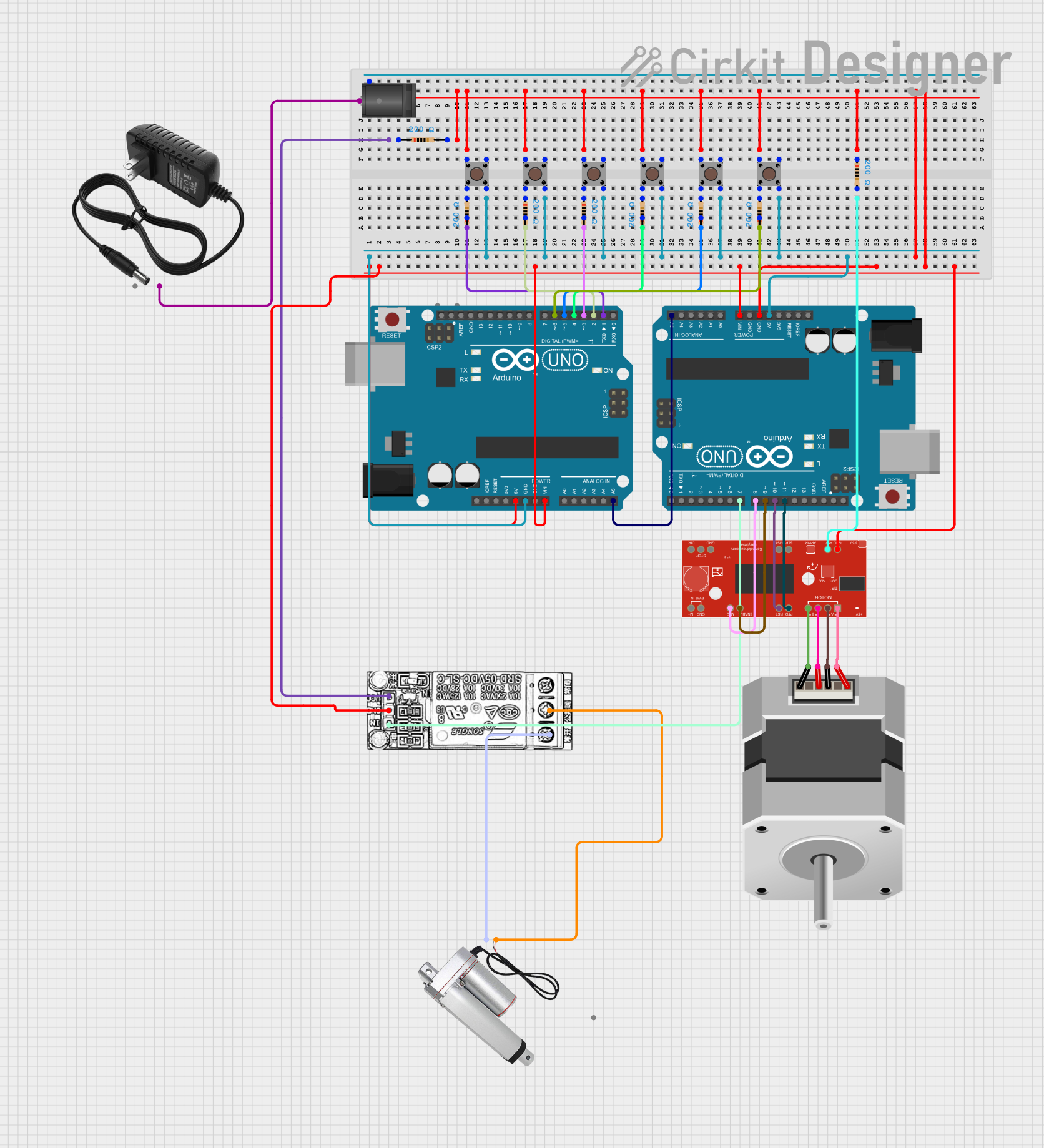
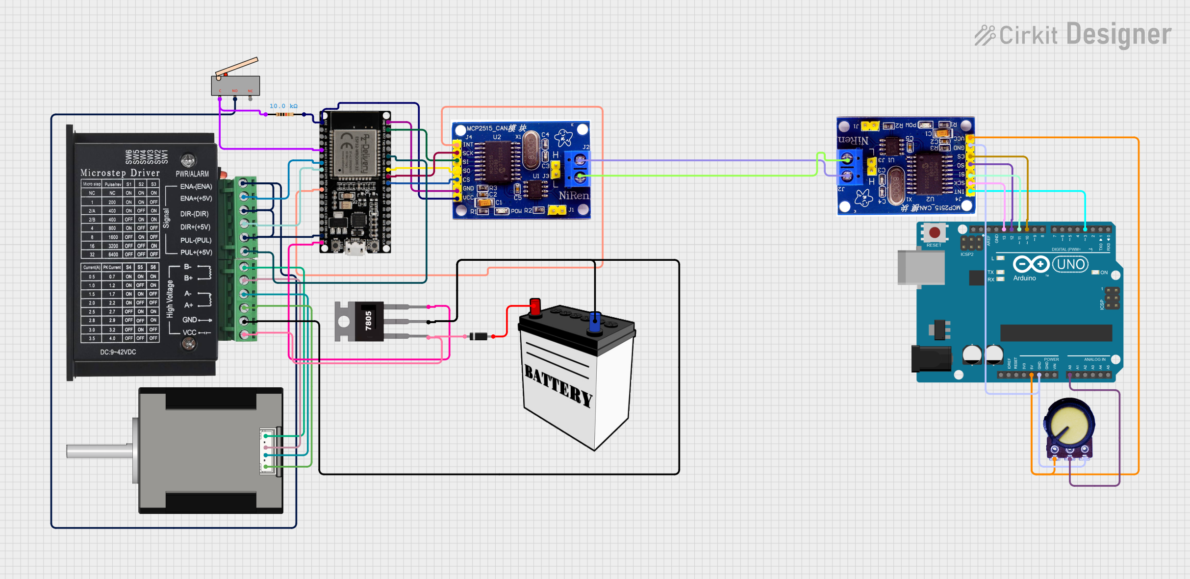

Explore Projects Built with Integrated Step Driver
Common Applications and Use Cases
- CNC machines and 3D printers
- Robotics and automation systems
- Conveyor belts and material handling
- Medical devices requiring precise motion control
- Surveillance systems with pan/tilt mechanisms
Technical Specifications
The following table outlines the key technical details of the ISD04 Integrated Step Driver:
| Parameter | Value |
|---|---|
| Input Voltage Range | 10-40 VDC |
| Maximum Output Current | 4 A |
| Microstepping Resolution | Up to 1/256 steps |
| Control Signal Type | Pulse/Direction or CW/CCW |
| Input Signal Voltage | 3.3V or 5V logic compatible |
| Operating Temperature | -10°C to +45°C |
| Dimensions | 118 mm x 75 mm x 34 mm |
| Weight | 300 g |
Pin Configuration and Descriptions
The ISD04 Integrated Step Driver features the following pin configuration:
Power and Motor Connections
| Pin Name | Description |
|---|---|
| V+ | Positive power supply input (10-40 VDC) |
| GND | Ground connection for power supply |
| A+ | Motor phase A positive terminal |
| A- | Motor phase A negative terminal |
| B+ | Motor phase B positive terminal |
| B- | Motor phase B negative terminal |
Control Signal Connections
| Pin Name | Description |
|---|---|
| PUL+ | Pulse signal input (positive) |
| PUL- | Pulse signal input (negative) |
| DIR+ | Direction signal input (positive) |
| DIR- | Direction signal input (negative) |
| ENA+ | Enable signal input (positive) |
| ENA- | Enable signal input (negative) |
Usage Instructions
How to Use the Component in a Circuit
- Power Supply: Connect a DC power supply (10-40 VDC) to the
V+andGNDpins. Ensure the power supply can provide sufficient current for the motor and driver. - Motor Connection: Connect the stepper motor's phase wires to the
A+,A-,B+, andB-terminals. Verify the motor's wiring to avoid incorrect connections. - Control Signals:
- Connect the
PUL+andPUL-pins to the pulse signal source (e.g., a microcontroller or PLC). - Connect the
DIR+andDIR-pins to the direction signal source. - Optionally, connect the
ENA+andENA-pins to an enable signal source. If unused, leave these pins unconnected.
- Connect the
- Microstepping Configuration: Use the onboard DIP switches to set the desired microstepping resolution. Refer to the manufacturer's datasheet for the DIP switch settings.
- Test the Setup: Power on the system and send pulse and direction signals to the driver. Observe the motor's movement to ensure proper operation.
Important Considerations and Best Practices
- Current Setting: Adjust the current limit on the driver to match the stepper motor's rated current. This prevents overheating and ensures optimal performance.
- Signal Voltage Compatibility: Ensure the control signals are compatible with the driver's input voltage (3.3V or 5V logic).
- Cooling: Provide adequate ventilation or a heatsink to prevent the driver from overheating during prolonged operation.
- Wiring: Use shielded cables for control signals to minimize electromagnetic interference (EMI).
Example Code for Arduino UNO
Below is an example of how to control the ISD04 Integrated Step Driver using an Arduino UNO:
// Define pin connections
const int pulsePin = 2; // Connect to PUL+ (PUL- to GND)
const int dirPin = 3;   // Connect to DIR+ (DIR- to GND)
const int enablePin = 4; // Connect to ENA+ (ENA- to GND)

void setup() {
  // Set pin modes
  pinMode(pulsePin, OUTPUT);
  pinMode(dirPin, OUTPUT);
  pinMode(enablePin, OUTPUT);

  // Enable the driver
  digitalWrite(enablePin, LOW); // LOW to enable, HIGH to disable
}

void loop() {
  // Set direction
  digitalWrite(dirPin, HIGH); // HIGH for one direction, LOW for the other

  // Generate pulses to move the motor
  for (int i = 0; i < 200; i++) { // 200 steps for one revolution (example)
    digitalWrite(pulsePin, HIGH);
    delayMicroseconds(500); // Adjust for speed control
    digitalWrite(pulsePin, LOW);
    delayMicroseconds(500);
  }

  delay(1000); // Wait before changing direction

  // Change direction
  digitalWrite(dirPin, LOW);

  // Generate pulses in the opposite direction
  for (int i = 0; i < 200; i++) {
    digitalWrite(pulsePin, HIGH);
    delayMicroseconds(500);
    digitalWrite(pulsePin, LOW);
    delayMicroseconds(500);
  }

  delay(1000); // Wait before repeating
}
Troubleshooting and FAQs
Common Issues and Solutions
Motor Not Moving:
- Verify the power supply voltage and current are within the specified range.
- Check the motor wiring for correct connections to the driver.
- Ensure the pulse and direction signals are being sent correctly.
Overheating:
- Reduce the current limit setting on the driver.
- Improve ventilation or add a heatsink to the driver.
Erratic Motor Movement:
- Check for loose or faulty wiring.
- Use shielded cables for control signals to reduce EMI.
- Verify the microstepping settings on the DIP switches.
Driver Not Enabling:
- Ensure the enable signal (
ENA+andENA-) is correctly connected or left unconnected if not used. - Check the logic level of the enable signal (LOW to enable).
- Ensure the enable signal (
FAQs
Can I use a 24V power supply with this driver? Yes, the driver supports a voltage range of 10-40 VDC, so 24V is within the acceptable range.
What happens if I exceed the current limit? Exceeding the current limit may damage the driver or motor. Always set the current limit to match the motor's rated current.
Can I use this driver with a NEMA 23 stepper motor? Yes, as long as the motor's voltage and current ratings are compatible with the driver's specifications.
Is the driver compatible with 3.3V logic signals? Yes, the driver supports both 3.3V and 5V logic levels for control signals.