
How to Use FIT0521: Examples, Pinouts, and Specs
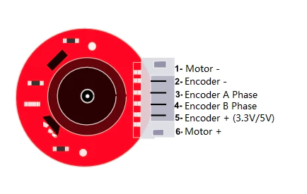
 Design with FIT0521 in Cirkit Designer
Introduction
The FIT0521, manufactured by DFRobot, is a versatile integrated circuit (IC) designed for specialized applications, particularly in signal processing and control systems. This component is known for its low power consumption and high efficiency, making it an excellent choice for portable and battery-powered devices. Its robust design and reliable performance make it a popular option for engineers and hobbyists alike.
Explore Projects Built with FIT0521
 Open Project in Cirkit Designer
 Open Project in Cirkit Designer
 Open Project in Cirkit Designer
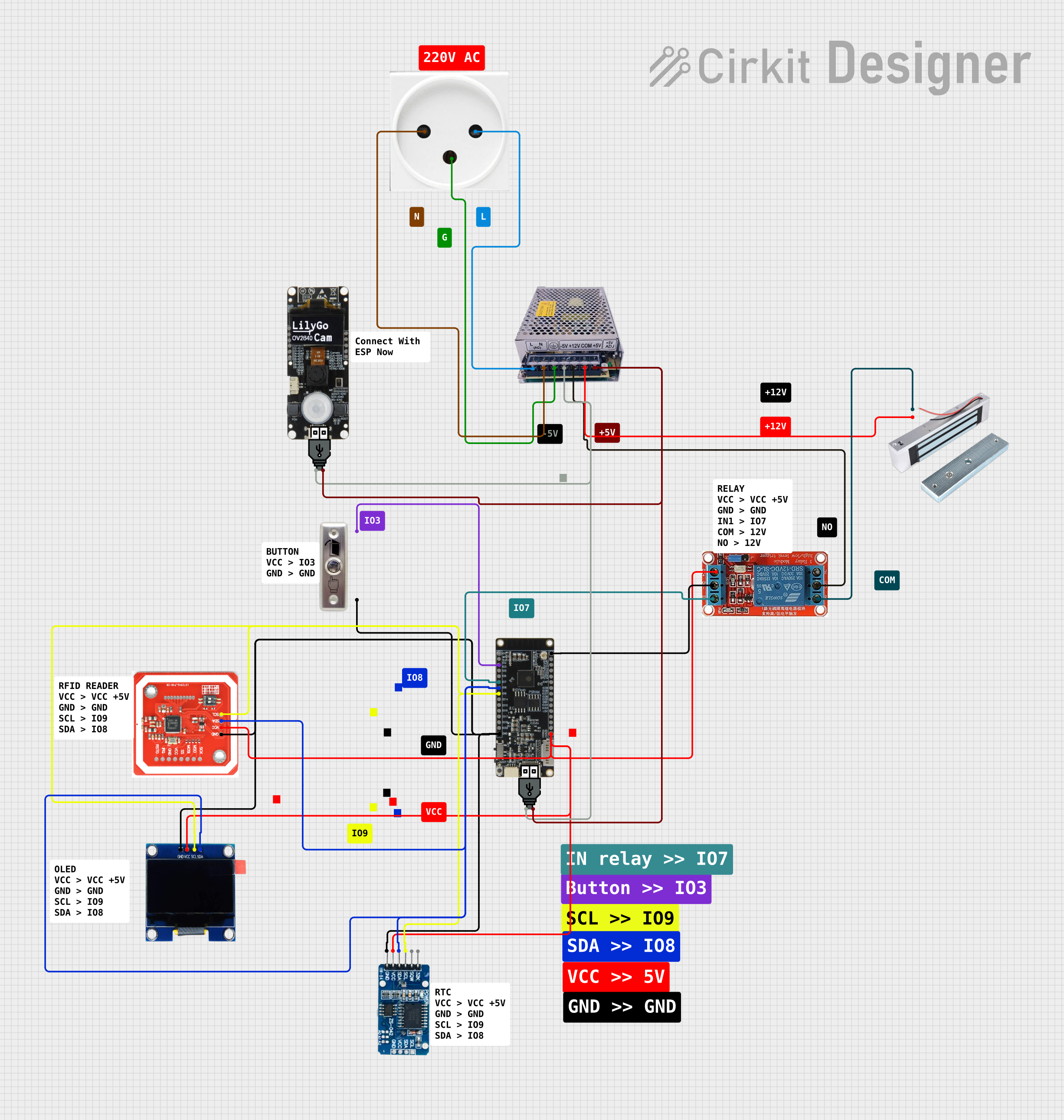 Open Project in Cirkit Designer
Explore Projects Built with FIT0521
Open Project in Cirkit DesignerOpen Project in Cirkit DesignerOpen Project in Cirkit DesignerOpen Project in Cirkit DesignerCommon Applications and Use Cases
- Signal processing in audio or communication systems
- Motor control in robotics and automation
- Power management in portable devices
- Embedded systems requiring efficient control logic
Technical Specifications
Below are the key technical details of the FIT0521:
| Parameter | Value |
|---|---|
| Manufacturer | DFRobot |
| Part Number | FIT0521 |
| Operating Voltage | 3.3V to 5V |
| Operating Current | 10mA (typical) |
| Power Consumption | Low (optimized for efficiency) |
| Operating Temperature | -40°C to 85°C |
| Package Type | DIP/SOP |
| Application Type | Signal processing, control |
Pin Configuration and Descriptions
The FIT0521 features a standard pinout for ease of integration. Below is the pin configuration:
| Pin Number | Pin Name | Description |
|---|---|---|
| 1 | VCC | Power supply input (3.3V to 5V) |
| 2 | GND | Ground connection |
| 3 | IN1 | Input signal 1 |
| 4 | IN2 | Input signal 2 |
| 5 | OUT1 | Output signal 1 |
| 6 | OUT2 | Output signal 2 |
| 7 | ENABLE | Enable pin for activating the IC |
| 8 | NC | Not connected (reserved for future use) |
Usage Instructions
How to Use the FIT0521 in a Circuit
- Power Supply: Connect the VCC pin to a stable power source (3.3V to 5V) and the GND pin to the ground of your circuit.
- Input Signals: Provide input signals to the IN1 and IN2 pins. These signals can be analog or digital, depending on your application.
- Output Signals: The processed signals will be available at the OUT1 and OUT2 pins. Connect these to the desired load or next stage in your circuit.
- Enable Pin: Ensure the ENABLE pin is set high to activate the IC. If left low, the IC will remain in a low-power standby mode.
Important Considerations and Best Practices
- Decoupling Capacitors: Place a 0.1µF ceramic capacitor close to the VCC pin to filter out noise and ensure stable operation.
- Signal Integrity: Use shielded cables or proper PCB layout techniques to minimize noise interference on the input signals.
- Thermal Management: Although the FIT0521 is efficient, ensure adequate ventilation or heat dissipation if used in high-temperature environments.
- Arduino Compatibility: The FIT0521 can be easily interfaced with an Arduino UNO for control and signal processing tasks.
Example Arduino Code
Below is an example of how to use the FIT0521 with an Arduino UNO to process input signals and control outputs:
// Define pin connections for the FIT0521
const int enablePin = 7;  // Connect to ENABLE pin of FIT0521
const int input1Pin = 8;  // Connect to IN1 pin of FIT0521
const int input2Pin = 9;  // Connect to IN2 pin of FIT0521
const int output1Pin = 10; // Connect to OUT1 pin of FIT0521
const int output2Pin = 11; // Connect to OUT2 pin of FIT0521

void setup() {
  // Initialize pins
  pinMode(enablePin, OUTPUT);
  pinMode(input1Pin, OUTPUT);
  pinMode(input2Pin, OUTPUT);
  pinMode(output1Pin, INPUT);
  pinMode(output2Pin, INPUT);

  // Enable the FIT0521
  digitalWrite(enablePin, HIGH); // Set ENABLE pin high to activate the IC
}

void loop() {
  // Example: Send signals to IN1 and IN2
  digitalWrite(input1Pin, HIGH); // Set IN1 high
  digitalWrite(input2Pin, LOW);  // Set IN2 low

  // Read processed signals from OUT1 and OUT2
  int output1 = digitalRead(output1Pin);
  int output2 = digitalRead(output2Pin);

  // Add your application logic here
  delay(1000); // Wait for 1 second
}
Troubleshooting and FAQs
Common Issues and Solutions
No Output Signal:
- Ensure the ENABLE pin is set high to activate the IC.
- Verify that the input signals are within the acceptable voltage range.
Excessive Noise in Output:
- Add decoupling capacitors near the VCC pin.
- Check for proper grounding and minimize interference from nearby components.
Overheating:
- Ensure the IC is not exposed to voltages beyond its rated limits.
- Provide adequate ventilation or heat sinks if necessary.
Arduino Not Responding:
- Double-check the pin connections between the Arduino and the FIT0521.
- Ensure the Arduino code is correctly uploaded and the board is powered.
FAQs
Q: Can the FIT0521 handle PWM signals?
A: Yes, the FIT0521 can process PWM signals, making it suitable for motor control and other applications requiring variable signal modulation.
Q: Is the FIT0521 compatible with 3.3V logic?
A: Yes, the FIT0521 operates within a voltage range of 3.3V to 5V, making it compatible with both 3.3V and 5V logic systems.
Q: What is the maximum current the FIT0521 can handle?
A: The FIT0521 typically operates at 10mA, but ensure your circuit design does not exceed the manufacturer's specified limits.
By following this documentation, users can effectively integrate the FIT0521 into their projects and troubleshoot common issues with ease.