How to Use T-Display-S3: Examples, Pinouts, and Specs
Introduction
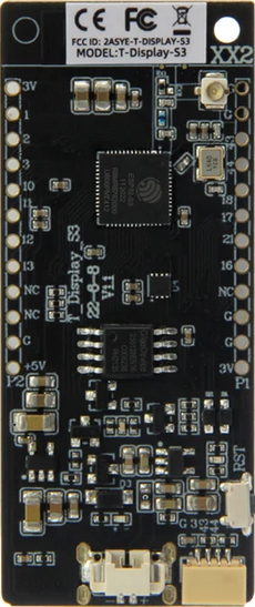
The T-Display-S3 by Lilygo (Manufacturer Part ID: Lilygo ESP32-S3) is a compact display module featuring a 1.14-inch TFT screen. It is powered by the ESP32-S3 microcontroller, which provides robust processing capabilities and wireless connectivity (Wi-Fi and Bluetooth). This module is designed for projects requiring graphical output, making it ideal for IoT devices, portable displays, and user interfaces.
Explore Projects Built with T-Display-S3
Explore Projects Built with T-Display-S3
Common Applications and Use Cases
- IoT dashboards and monitoring systems
- Wearable devices with graphical interfaces
- Portable gaming consoles
- Smart home control panels
- Educational and prototyping projects
Technical Specifications
Key Technical Details
| Parameter | Specification |
|---|---|
| Microcontroller | ESP32-S3 |
| Display Type | 1.14-inch TFT LCD |
| Resolution | 135 x 240 pixels |
| Display Driver | ST7789 |
| Communication Interface | SPI |
| Operating Voltage | 3.3V |
| Power Supply | USB-C (5V) |
| Wireless Connectivity | Wi-Fi 802.11 b/g/n, Bluetooth 5.0 |
| Flash Memory | 16MB |
| PSRAM | 8MB |
| GPIO Pins | 14 (including I2C, SPI, UART support) |
| Dimensions | 51mm x 25mm |
Pin Configuration and Descriptions
| Pin Name | Pin Number | Description |
|---|---|---|
| GND | - | Ground |
| 3V3 | - | 3.3V Power Output |
| GPIO0 | 0 | General Purpose I/O, Boot Mode Select |
| GPIO1 | 1 | General Purpose I/O |
| GPIO2 | 2 | General Purpose I/O |
| GPIO3 | 3 | General Purpose I/O |
| GPIO4 | 4 | General Purpose I/O |
| GPIO5 | 5 | General Purpose I/O |
| SDA | 21 | I2C Data Line |
| SCL | 22 | I2C Clock Line |
| MOSI | 23 | SPI Master Out, Slave In |
| MISO | 19 | SPI Master In, Slave Out |
| SCK | 18 | SPI Clock |
| CS | 5 | SPI Chip Select |
Usage Instructions
How to Use the T-Display-S3 in a Circuit
- Powering the Module: Connect the module to a 5V USB-C power source. The onboard voltage regulator will step down the voltage to 3.3V for internal use.
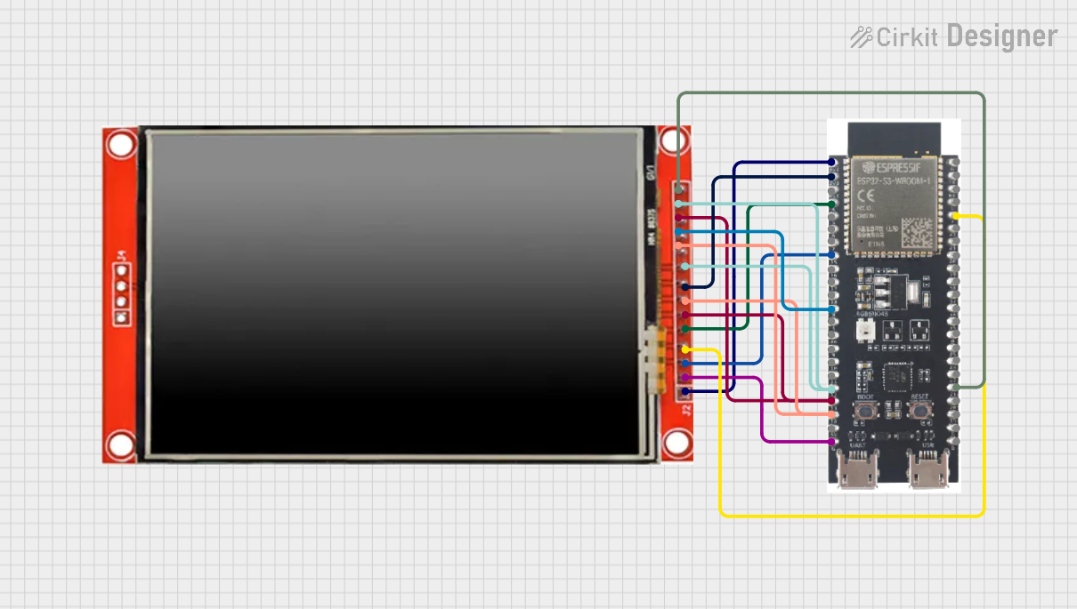
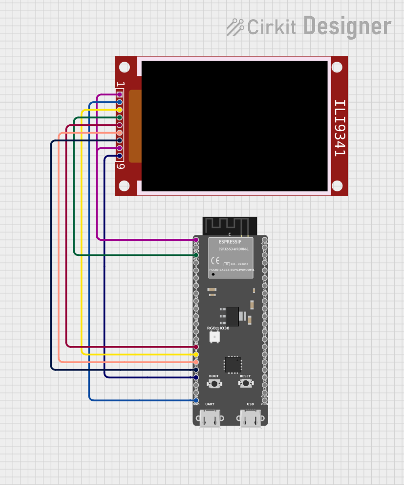
- Connecting to a Microcontroller: Use the SPI interface to communicate with the display. Ensure the correct pins (MOSI, MISO, SCK, CS) are connected to the corresponding pins on your microcontroller.
- Programming: The T-Display-S3 can be programmed using the Arduino IDE or ESP-IDF. Install the necessary libraries (e.g.,
TFT_eSPI) to control the display.
Important Considerations and Best Practices
- Voltage Levels: Ensure all GPIO pins operate at 3.3V logic levels to avoid damaging the module.
- Library Configuration: When using the
TFT_eSPIlibrary, configure theUser_Setup.hfile to match the T-Display-S3's pinout and display driver (ST7789). - Heat Management: The ESP32-S3 can generate heat during operation. Ensure proper ventilation if used in an enclosed space.
- Power Supply: Use a stable 5V power source to avoid unexpected resets or performance issues.
Example Code for Arduino UNO
Below is an example of how to display text on the T-Display-S3 using the Arduino IDE and the TFT_eSPI library:
#include <TFT_eSPI.h> // Include the TFT library

TFT_eSPI tft = TFT_eSPI(); // Create an instance of the display

void setup() {
  tft.init(); // Initialize the display
  tft.setRotation(1); // Set display orientation (1 = landscape)
  tft.fillScreen(TFT_BLACK); // Clear the screen with black color

  tft.setTextColor(TFT_WHITE, TFT_BLACK); // Set text color (white on black)
  tft.setTextSize(2); // Set text size

  tft.setCursor(10, 10); // Set cursor position
  tft.println("Hello, T-Display-S3!"); // Print text to the display
}

void loop() {
  // No actions in the loop for this example
}
Troubleshooting and FAQs
Common Issues and Solutions
Display Not Turning On:
- Ensure the module is properly powered (check the USB-C connection).
- Verify that the SPI connections are correct and secure.
No Output on the Display:
- Check the
User_Setup.hfile in theTFT_eSPIlibrary to ensure the correct pin configuration and driver (ST7789) are selected. - Confirm that the display initialization code (
tft.init()) is included in your sketch.
- Check the
Wi-Fi or Bluetooth Not Working:
- Ensure the ESP32-S3 firmware is correctly flashed.
- Verify that the Wi-Fi credentials or Bluetooth pairing settings are correct.
Module Overheating:
- Avoid running the module at maximum performance for extended periods.
- Use a heatsink or ensure proper ventilation.
FAQs
Can I use the T-Display-S3 with other microcontrollers? Yes, as long as the microcontroller supports SPI communication and operates at 3.3V logic levels.
What is the maximum resolution supported by the display? The display resolution is fixed at 135 x 240 pixels.
Is the T-Display-S3 compatible with CircuitPython? Yes, the T-Display-S3 can be programmed using CircuitPython with the appropriate libraries.
Can I power the module directly with a battery? Yes, you can use a 3.7V LiPo battery with a suitable charging circuit, but ensure the voltage is regulated to 3.3V for the ESP32-S3.
This concludes the documentation for the T-Display-S3. For further assistance, refer to the official Lilygo documentation or community forums.