How to Use TRANSFORMER: Examples, Pinouts, and Specs
Introduction
A transformer is a passive electrical device that transfers electrical energy from one electrical circuit to another through the process of electromagnetic induction. It is designed to change alternating current (AC) from one voltage level to another, which is achieved by winding two or more coils of wire around a core made of steel or ferrite. Transformers are essential components in power distribution and are also widely used in electronic devices to step-up or step-down voltage levels, isolate circuits, and adjust impedance. Common applications include power supplies, audio systems, chargers, and electrical utilities.
Explore Projects Built with TRANSFORMER
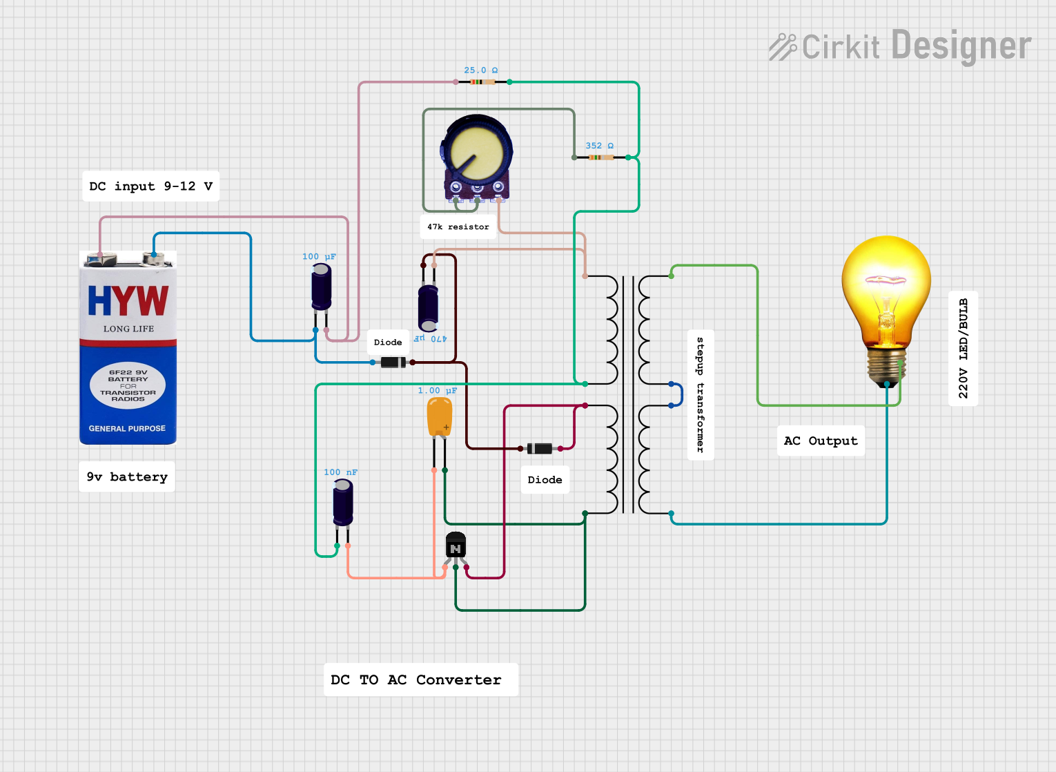


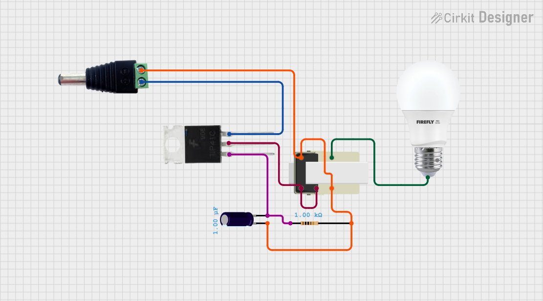
Explore Projects Built with TRANSFORMER
Technical Specifications
General Characteristics
- Type: Core-type or Shell-type
- Core Material: Silicon steel, Ferrite, Amorphous steel
- Frequency Range: Typically 50 Hz or 60 Hz for power transformers; up to hundreds of kHz for some electronic transformers
- Phase: Single-phase or Three-phase
Electrical Ratings
- Primary Voltage: Specified in volts (V)
- Secondary Voltage: Specified in volts (V)
- Rated Power: Specified in volt-amperes (VA) or kilovolt-amperes (kVA)
- Current Rating: Specified in amperes (A) for both primary and secondary windings
- Insulation Class: Class A, B, F, H, etc. (determines maximum operating temperature)
Pin Configuration and Descriptions
| Pin Number | Description | Notes |
|---|---|---|
| P1 | Primary Winding Start | Connect to AC voltage source |
| P2 | Primary Winding End | |
| S1 | Secondary Winding Start | Output AC voltage (lower or higher) |
| S2 | Secondary Winding End |
Note: Pin numbers and configurations may vary depending on the type and design of the transformer.
Usage Instructions
Integration into a Circuit
- Identify Voltage Requirements: Determine the voltage levels required for both the primary and secondary sides of the transformer.
- Connect Primary Winding: Connect the primary winding (P1 and P2) to the AC voltage source, ensuring it matches the transformer's rated primary voltage.
- Connect Secondary Winding: Connect the secondary winding (S1 and S2) to the load circuit. The secondary voltage will be stepped up or down based on the transformer's turns ratio.
- Grounding: Properly ground the transformer to prevent electrical shock and interference.
- Testing: Before applying full power, test the transformer with a multimeter to ensure correct voltage levels on the secondary side.
Best Practices
- Avoid Overloading: Do not exceed the rated power of the transformer to prevent overheating and potential failure.
- Cooling: Ensure adequate cooling for the transformer, especially for high-power applications.
- Isolation: Use transformers to provide galvanic isolation between circuits for safety and noise reduction.
- Mounting: Secure the transformer to prevent movement and reduce mechanical stress on the connections.
Troubleshooting and FAQs
Common Issues
- No Output Voltage: Check the input voltage and connections. Ensure the primary winding is not open-circuited.
- Overheating: Ensure the load does not exceed the transformer's rating. Check for short circuits on the secondary side.
- Humming Noise: Verify that the transformer is securely mounted. Check for loose laminations in the core.
FAQs
Q: Can a transformer convert DC to AC or vice versa? A: No, transformers only work with AC. For DC, you would need a converter or inverter.
Q: How do I know if my transformer is working properly? A: Measure the output voltage with a multimeter. It should match the expected secondary voltage based on the transformer's specifications.
Q: Can I use a transformer to change the frequency of the AC supply? A: No, a transformer cannot change the frequency. It only changes the voltage level.
Q: What does 'turns ratio' mean? A: The turns ratio is the ratio of the number of turns in the primary winding to the number of turns in the secondary winding. It determines the voltage transformation ratio.
For further assistance or technical support, please contact the manufacturer or a professional electrician.