How to Use ISOLATOR SWITCH: Examples, Pinouts, and Specs
Introduction
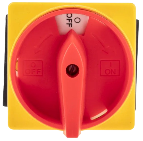
An isolator switch, manufactured by ISOLATOR SWITCH (Part ID: ISOLATOR SWITCH), is a mechanical device designed to ensure that an electrical circuit is completely de-energized for maintenance or safety purposes. It provides a visible and reliable break in the circuit, making it an essential component in high-voltage and industrial applications.
Explore Projects Built with ISOLATOR SWITCH


Explore Projects Built with ISOLATOR SWITCH
Common Applications and Use Cases
- Electrical maintenance and repair operations
- High-voltage power distribution systems
- Industrial machinery and equipment
- Renewable energy systems (e.g., solar and wind power installations)
- Emergency power isolation in critical systems
Technical Specifications
Key Technical Details
| Parameter | Value/Description |
|---|---|
| Rated Voltage | Up to 36 kV (varies by model) |
| Rated Current | 16 A to 3150 A (varies by model) |
| Insulation Resistance | ≥ 10 MΩ |
| Operating Temperature | -25°C to +70°C |
| Mechanical Endurance | ≥ 10,000 operations |
| Mounting Type | Panel-mounted or DIN rail-mounted |
| Contact Material | Silver-plated copper |
| Enclosure Protection | IP20 to IP65 (depending on model) |
Pin Configuration and Descriptions
Isolator switches typically do not have "pins" in the traditional sense, as they are mechanical devices. However, they feature terminals for electrical connections. Below is a general description of the terminal configuration:
| Terminal Label | Description |
|---|---|
| L1, L2, L3 | Input terminals for three-phase power supply |
| T1, T2, T3 | Output terminals for three-phase load connection |
| Earth (E) | Grounding terminal for safety |
| Auxiliary Contacts | Optional terminals for control circuit integration |
Usage Instructions
How to Use the Component in a Circuit
- Selection: Choose an isolator switch rated for the voltage and current of your application. Ensure the enclosure protection (IP rating) matches the environmental conditions.
- Installation:
- Mount the isolator switch securely on a panel or DIN rail.
- Connect the input power supply to the L1, L2, and L3 terminals.
- Connect the load to the T1, T2, and T3 terminals.
- Attach the grounding wire to the Earth (E) terminal.
- Operation:
- Turn the handle to the "ON" position to energize the circuit.
- Turn the handle to the "OFF" position to de-energize the circuit. Ensure the visible break is clear before proceeding with maintenance.
Important Considerations and Best Practices
- Always verify that the isolator switch is in the "OFF" position before performing maintenance.
- Use isolator switches with appropriate IP ratings for outdoor or harsh environments.
- Regularly inspect the switch for signs of wear, corrosion, or damage.
- For high-voltage applications, ensure compliance with local electrical safety standards.
Arduino Integration
Isolator switches are not typically used directly with microcontrollers like Arduino. However, auxiliary contacts on the isolator switch can be used to signal the switch's status to an Arduino. Below is an example of how to read the status of an auxiliary contact:
// Example code to read the status of an isolator switch's auxiliary contact
const int auxContactPin = 2; // Pin connected to the auxiliary contact
int switchStatus = 0;       // Variable to store the switch status

void setup() {
  pinMode(auxContactPin, INPUT_PULLUP); // Configure pin as input with pull-up
  Serial.begin(9600);                  // Initialize serial communication
}

void loop() {
  switchStatus = digitalRead(auxContactPin); // Read the auxiliary contact status

  if (switchStatus == LOW) {
    // Auxiliary contact is closed, isolator switch is ON
    Serial.println("Isolator Switch is ON");
  } else {
    // Auxiliary contact is open, isolator switch is OFF
    Serial.println("Isolator Switch is OFF");
  }

  delay(500); // Wait for 500ms before reading again
}
Troubleshooting and FAQs
Common Issues and Solutions
| Issue | Possible Cause | Solution |
|---|---|---|
| Switch does not operate smoothly | Mechanical wear or debris in mechanism | Clean and lubricate the mechanism. |
| Circuit remains energized when OFF | Faulty or welded contacts | Inspect and replace damaged contacts. |
| Visible break is not clear | Misalignment of internal components | Adjust or replace the isolator switch. |
| Auxiliary contact not working | Loose or incorrect wiring | Verify and secure all auxiliary wiring. |
FAQs
Can an isolator switch be used as a circuit breaker?
No, an isolator switch is not designed to interrupt current under load. It should only be operated when the circuit is de-energized.What is the difference between an isolator switch and a disconnect switch?
The terms are often used interchangeably, but an isolator switch typically emphasizes a visible break for safety, while a disconnect switch may include load-breaking capabilities.How often should an isolator switch be inspected?
Regular inspections should be conducted every 6-12 months, or more frequently in harsh environments.Can an isolator switch be used outdoors?
Yes, provided it has an appropriate IP rating (e.g., IP65) for protection against dust and water.
By following this documentation, users can safely and effectively integrate the ISOLATOR SWITCH into their electrical systems.