Cirkit Designer Logo
Cirkit Designer
Your all-in-one circuit design IDE
Home / 
Component Documentation

How to Use 0-50V 4A DC power supply filter board: Examples, Pinouts, and Specs

Image of 0-50V 4A DC power supply filter board
Cirkit Designer LogoDesign with 0-50V 4A DC power supply filter board in Cirkit Designer

Introduction

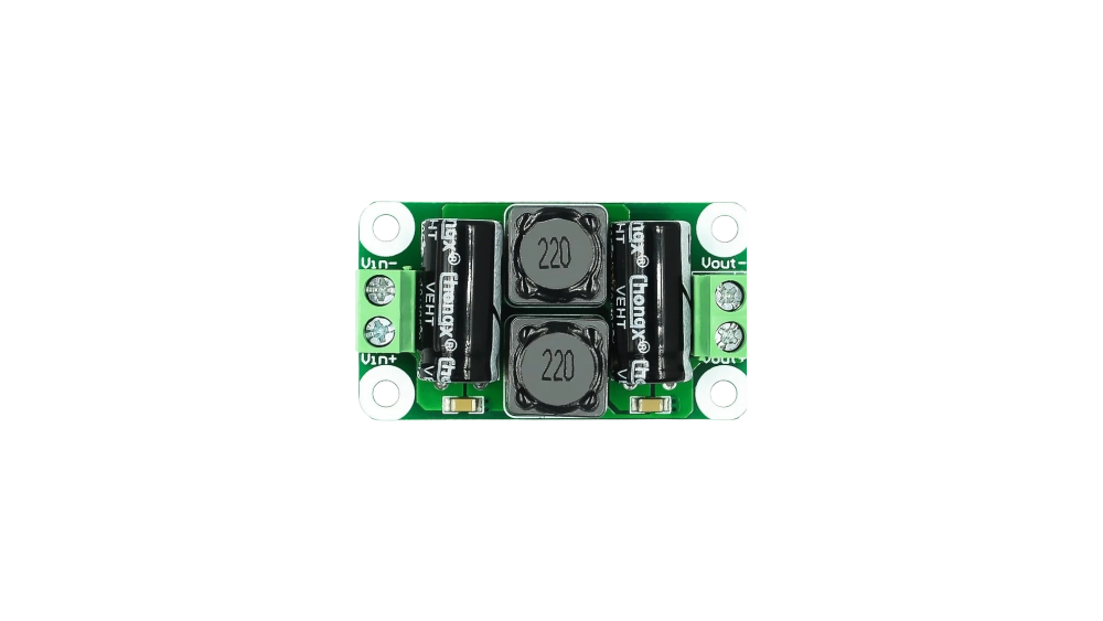
The 0-50V 4A DC Power Supply Filter Board, manufactured in Mainland China, is a versatile circuit board designed to filter and stabilize the output of a DC power supply. It ensures clean and reliable power delivery by reducing noise, ripple, and other unwanted fluctuations in the power supply. This component is ideal for applications requiring stable DC power, such as powering sensitive electronic devices, audio equipment, and microcontroller-based systems.

Explore Projects Built with 0-50V 4A DC power supply filter board

Use Cirkit Designer to design, explore, and prototype these projects online. Some projects support real-time simulation. Click "Open Project" to start designing instantly!
AC to DC Power Supply with 7-Segment Voltage Display
Image of BEE PBL: A project utilizing 0-50V 4A DC power supply filter board in a practical application
This circuit is a regulated power supply that converts 220V AC to a lower, stable DC voltage. It includes a step-down transformer, bridge rectifier, voltage regulator, and filtering capacitors. A 7-segment display indicates the output voltage, which can be adjusted using a potentiometer.
Cirkit Designer LogoOpen Project in Cirkit Designer
AC to DC Power Supply with Built-In Volt/Ammeter
Image of Variable DC: A project utilizing 0-50V 4A DC power supply filter board in a practical application
This circuit appears to be a power supply unit that converts AC voltage to a rectified DC output. It uses a power transformer to step down the AC voltage, which is then rectified by a bridge rectifier composed of four diodes. An electrolytic capacitor is used for smoothing the rectified output, and a mini digital volt/ammeter is included to monitor the voltage and current. The circuit also includes a rocker switch for power control, an AC power plug as the input, and a DC female jack and BNC connectors as outputs.
Cirkit Designer LogoOpen Project in Cirkit Designer
AC to DC Power Supply with Voltage Regulation and LED Indicator
Image of Copy of 8 volt AC to DC convertor (1): A project utilizing 0-50V 4A DC power supply filter board in a practical application
This circuit is a basic AC to DC power supply with voltage regulation. It includes a transformer to step down the AC voltage, a bridge rectifier made of 1N4007 diodes to convert AC to DC, an electrolytic capacitor for smoothing, and a voltage regulator to provide a stable DC output. An LED with a current-limiting resistor indicates the presence of the output voltage.
Cirkit Designer LogoOpen Project in Cirkit Designer
12V to 5V Power Supply with LED Indicator and Push Switch
Image of Power Supply LVCO: A project utilizing 0-50V 4A DC power supply filter board in a practical application
This circuit is a 12V to 5V regulated power supply with an LED indicator. It uses a 5408 diode for reverse polarity protection, an LM340T5 7805 voltage regulator to step down the voltage to 5V, and a push switch to control the LED indicator. The circuit also includes capacitors for filtering and a resistor to limit the current through the LED.
Cirkit Designer LogoOpen Project in Cirkit Designer

Explore Projects Built with 0-50V 4A DC power supply filter board

Use Cirkit Designer to design, explore, and prototype these projects online. Some projects support real-time simulation. Click "Open Project" to start designing instantly!
Image of BEE PBL: A project utilizing 0-50V 4A DC power supply filter board in a practical application
AC to DC Power Supply with 7-Segment Voltage Display
This circuit is a regulated power supply that converts 220V AC to a lower, stable DC voltage. It includes a step-down transformer, bridge rectifier, voltage regulator, and filtering capacitors. A 7-segment display indicates the output voltage, which can be adjusted using a potentiometer.
Cirkit Designer LogoOpen Project in Cirkit Designer
Image of Variable DC: A project utilizing 0-50V 4A DC power supply filter board in a practical application
AC to DC Power Supply with Built-In Volt/Ammeter
This circuit appears to be a power supply unit that converts AC voltage to a rectified DC output. It uses a power transformer to step down the AC voltage, which is then rectified by a bridge rectifier composed of four diodes. An electrolytic capacitor is used for smoothing the rectified output, and a mini digital volt/ammeter is included to monitor the voltage and current. The circuit also includes a rocker switch for power control, an AC power plug as the input, and a DC female jack and BNC connectors as outputs.
Cirkit Designer LogoOpen Project in Cirkit Designer
Image of Copy of 8 volt AC to DC convertor (1): A project utilizing 0-50V 4A DC power supply filter board in a practical application
AC to DC Power Supply with Voltage Regulation and LED Indicator
This circuit is a basic AC to DC power supply with voltage regulation. It includes a transformer to step down the AC voltage, a bridge rectifier made of 1N4007 diodes to convert AC to DC, an electrolytic capacitor for smoothing, and a voltage regulator to provide a stable DC output. An LED with a current-limiting resistor indicates the presence of the output voltage.
Cirkit Designer LogoOpen Project in Cirkit Designer
Image of Power Supply LVCO: A project utilizing 0-50V 4A DC power supply filter board in a practical application
12V to 5V Power Supply with LED Indicator and Push Switch
This circuit is a 12V to 5V regulated power supply with an LED indicator. It uses a 5408 diode for reverse polarity protection, an LM340T5 7805 voltage regulator to step down the voltage to 5V, and a push switch to control the LED indicator. The circuit also includes capacitors for filtering and a resistor to limit the current through the LED.
Cirkit Designer LogoOpen Project in Cirkit Designer

Common Applications and Use Cases

  • Powering microcontrollers and development boards (e.g., Arduino, Raspberry Pi)
  • Audio amplifiers and other audio equipment
  • Laboratory power supplies
  • Industrial control systems
  • LED lighting systems
  • Any application requiring low-noise, stable DC power

Technical Specifications

The following table outlines the key technical specifications of the 0-50V 4A DC Power Supply Filter Board:

Parameter Specification
Input Voltage Range 0-50V DC
Output Voltage Range 0-50V DC (same as input)
Maximum Current 4A
Ripple Reduction High efficiency
Dimensions Varies by manufacturer (e.g., 50x30mm)
Operating Temperature -20°C to 85°C
PCB Material FR4 (standard PCB material)

Pin Configuration and Descriptions

The filter board typically has the following pin configuration:

Pin Name Description
VIN+ Positive input voltage terminal
VIN- Negative input voltage terminal (ground)
VOUT+ Positive output voltage terminal
VOUT- Negative output voltage terminal (ground)

Usage Instructions

How to Use the Component in a Circuit

  1. Connect the Input Voltage:

    • Connect the positive terminal of your DC power supply to the VIN+ pin.
    • Connect the negative terminal of your DC power supply to the VIN- pin.
  2. Connect the Output Load:

    • Connect the positive terminal of your load (e.g., microcontroller, LED, etc.) to the VOUT+ pin.
    • Connect the negative terminal of your load to the VOUT- pin.
  3. Power On:

    • Turn on the DC power supply. The filter board will stabilize the input voltage and provide a clean output to your load.
  4. Verify Output:

    • Use a multimeter to measure the output voltage and ensure it matches the input voltage.

Important Considerations and Best Practices

  • Input Voltage Range: Ensure the input voltage does not exceed 50V DC to avoid damaging the board.
  • Current Limit: Do not exceed the maximum current rating of 4A to prevent overheating or failure.
  • Heat Dissipation: If operating near the maximum current, ensure adequate ventilation or use a heatsink to dissipate heat.
  • Polarity: Double-check the polarity of the input and output connections to avoid damage.
  • Capacitor Ratings: The onboard capacitors are rated for specific voltages. Do not exceed these ratings.

Example: Using with an Arduino UNO

To power an Arduino UNO with the filter board, follow these steps:

  1. Connect a 12V DC power supply to the VIN+ and VIN- pins of the filter board.
  2. Connect the VOUT+ and VOUT- pins to the Arduino's VIN and GND pins, respectively.
  3. Turn on the power supply. The filter board will provide a stable 12V to the Arduino.

Here is an example Arduino code to blink an LED while powered through the filter board:

// Simple LED Blink Example
// This code blinks an LED connected to pin 13 of the Arduino UNO.
// Ensure the Arduino is powered through the filter board for stable operation.

void setup() {
  pinMode(13, OUTPUT); // Set pin 13 as an output
}

void loop() {
  digitalWrite(13, HIGH); // Turn the LED on
  delay(1000);            // Wait for 1 second
  digitalWrite(13, LOW);  // Turn the LED off
  delay(1000);            // Wait for 1 second
}

Troubleshooting and FAQs

Common Issues and Solutions

Issue Possible Cause Solution
No output voltage Incorrect wiring or loose connections Verify all connections and polarity.
Excessive heat on the board Overcurrent or high input voltage Reduce load current or input voltage.
Output voltage fluctuates Insufficient input voltage stability Use a more stable DC power supply.
Noise or ripple in output High-frequency interference Add additional filtering capacitors.

FAQs

  1. Can this board handle AC input?

    • No, this board is designed for DC input only. Applying AC voltage will damage the board.
  2. What happens if I exceed the 4A current limit?

    • Exceeding the current limit may cause overheating, damage to the components, or failure of the board.
  3. Can I use this board with a battery?

    • Yes, the board can be used with a DC battery as long as the voltage is within the 0-50V range.
  4. Is the output voltage adjustable?

    • No, the output voltage is the same as the input voltage. This board is designed for filtering, not regulation.

By following this documentation, you can effectively use the 0-50V 4A DC Power Supply Filter Board in your projects to ensure clean and stable power delivery.