How to Use Flora LSM9DS0 9DOF: Examples, Pinouts, and Specs
Introduction
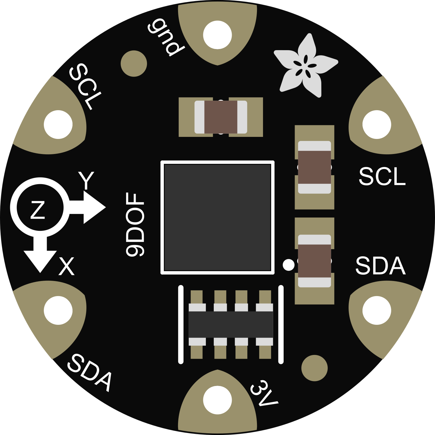
The Flora LSM9DS0 9DOF (9 Degrees of Freedom) sensor module is a versatile, multi-sensor component that integrates a 3-axis accelerometer, a 3-axis gyroscope, and a 3-axis magnetometer. This compact module is designed for motion sensing and orientation tracking in a wide range of applications, including wearable electronics, robotics, and gesture recognition. Its compatibility with the Adafruit Flora platform makes it an excellent choice for e-textiles and wearable projects.
Explore Projects Built with Flora LSM9DS0 9DOF

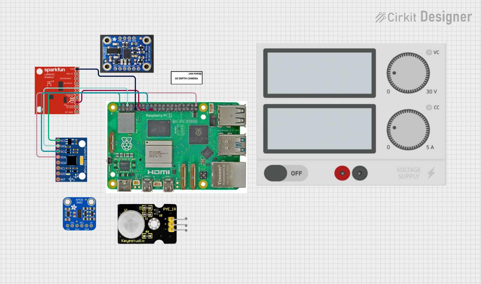

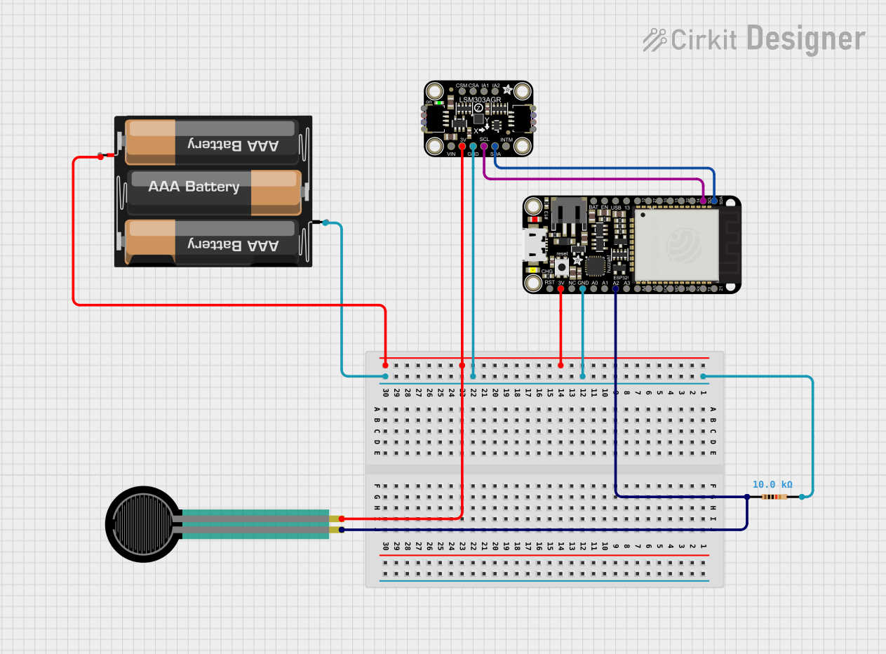
Explore Projects Built with Flora LSM9DS0 9DOF
Technical Specifications
Key Technical Details
- Supply Voltage (VDD): 2.4V to 3.6V
- Digital Output: I²C (up to 400 kHz) and SPI (up to 10 MHz)
- Operating Temperature Range: -40°C to 85°C
- Accelerometer Range: ±2/±4/±6/±8/±16 g
- Gyroscope Range: ±245/±500/±2000 dps (degrees per second)
- Magnetometer Range: ±2/±4/±8/±12 gauss
Pin Configuration and Descriptions
| Pin Number | Name | Description |
|---|---|---|
| 1 | GND | Ground connection |
| 2 | VIN | Supply voltage input (2.4V to 3.6V) |
| 3 | SCL | I²C clock line / SPI clock line |
| 4 | SDA | I²C data line / SPI data line for accelerometer and gyroscope |
| 5 | SDO/SA0 | SPI data output for magnetometer / I²C least significant bit of the address |
| 6 | CS_AG | Chip select for accelerometer and gyroscope (active low for SPI) |
| 7 | CS_M | Chip select for magnetometer (active low for SPI) |
Usage Instructions
Integration with a Circuit
To use the Flora LSM9DS0 9DOF sensor in a circuit:
- Connect the GND pin to the ground of your microcontroller.
- Connect the VIN pin to a voltage supply between 2.4V and 3.6V.
- For I²C communication, connect the SCL and SDA pins to the corresponding I²C clock and data lines on your microcontroller.
- For SPI communication, additionally connect the SDO/SA0, CS_AG, and CS_M pins to the appropriate SPI lines on your microcontroller.
Best Practices
- Ensure that the power supply is stable and within the specified voltage range.
- Use pull-up resistors on the I²C lines if they are not already present on your microcontroller board.
- When using SPI, ensure that the chip select pins are correctly managed to avoid communication conflicts.
- Place the sensor away from magnetic fields and vibration sources to prevent interference and noise.
Example Code for Arduino UNO
Below is an example code snippet for initializing the Flora LSM9DS0 9DOF sensor with an Arduino UNO using the I²C protocol. This code assumes the use of the Adafruit LSM9DS0 library.
#include <Wire.h>
#include <Adafruit_Sensor.h>
#include <Adafruit_LSM9DS0.h>

// Create an instance of the LSM9DS0 sensor
Adafruit_LSM9DS0 lsm = Adafruit_LSM9DS0();

void setup() {
  Serial.begin(9600);

  // Initialize the sensor
  if (!lsm.begin()) {
    Serial.println("Failed to find LSM9DS0 sensor");
    while (1);
  }
  Serial.println("LSM9DS0 sensor found!");
}

void loop() {
  // Read the sensor
  lsm.read();

  // Print accelerometer, gyroscope, and magnetometer data
  Serial.print("Accel X: "); Serial.print(lsm.accelData.x); Serial.print(" ");
  Serial.print("Y: "); Serial.print(lsm.accelData.y); Serial.print(" ");
  Serial.print("Z: "); Serial.println(lsm.accelData.z);

  Serial.print("Gyro X: "); Serial.print(lsm.gyroData.x); Serial.print(" ");
  Serial.print("Y: "); Serial.print(lsm.gyroData.y); Serial.print(" ");
  Serial.print("Z: "); Serial.println(lsm.gyroData.z);

  Serial.print("Mag X: "); Serial.print(lsm.magData.x); Serial.print(" ");
  Serial.print("Y: "); Serial.print(lsm.magData.y); Serial.print(" ");
  Serial.print("Z: "); Serial.println(lsm.magData.z);

  delay(1000);
}
Troubleshooting and FAQs
Common Issues
- Sensor not detected: Ensure that the wiring is correct and that the sensor is properly powered.
- Inaccurate readings: Calibrate the sensor and make sure it is placed in an environment free from magnetic interference and vibrations.
- I²C communication errors: Check for proper pull-up resistors and that no other device on the bus is conflicting with the sensor's address.
FAQs
Q: Can the sensor be used with a 5V microcontroller? A: Yes, but ensure that the VIN pin is connected to a voltage level within the sensor's operating range (2.4V to 3.6V).
Q: How do I calibrate the magnetometer? A: Calibration typically involves rotating the sensor in various orientations and using the collected data to adjust the readings. Refer to the sensor's datasheet and the library's documentation for specific calibration procedures.
Q: What is the default I²C address of the sensor? A: The default I²C address for the accelerometer and gyroscope is 0x1D (if SDO/SA0 is high) or 0x1E (if SDO/SA0 is low). The magnetometer has a fixed I²C address of 0x1E.
For further assistance, consult the sensor's datasheet and the Adafruit LSM9DS0 library documentation.