
How to Use Limit Switch: Examples, Pinouts, and Specs
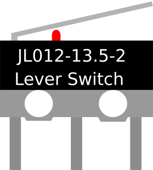
 Design with Limit Switch in Cirkit Designer
Introduction
A limit switch is an electromechanical device that detects the presence or absence of an object or the position of a moving part. It operates by making or breaking an electrical connection when a physical actuator is engaged. Limit switches are widely used in industrial automation, robotics, and safety systems to control machinery and provide feedback to control systems.
Explore Projects Built with Limit Switch
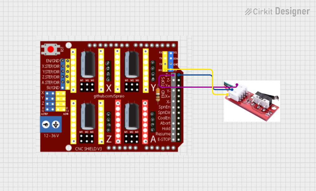 Open Project in Cirkit Designer
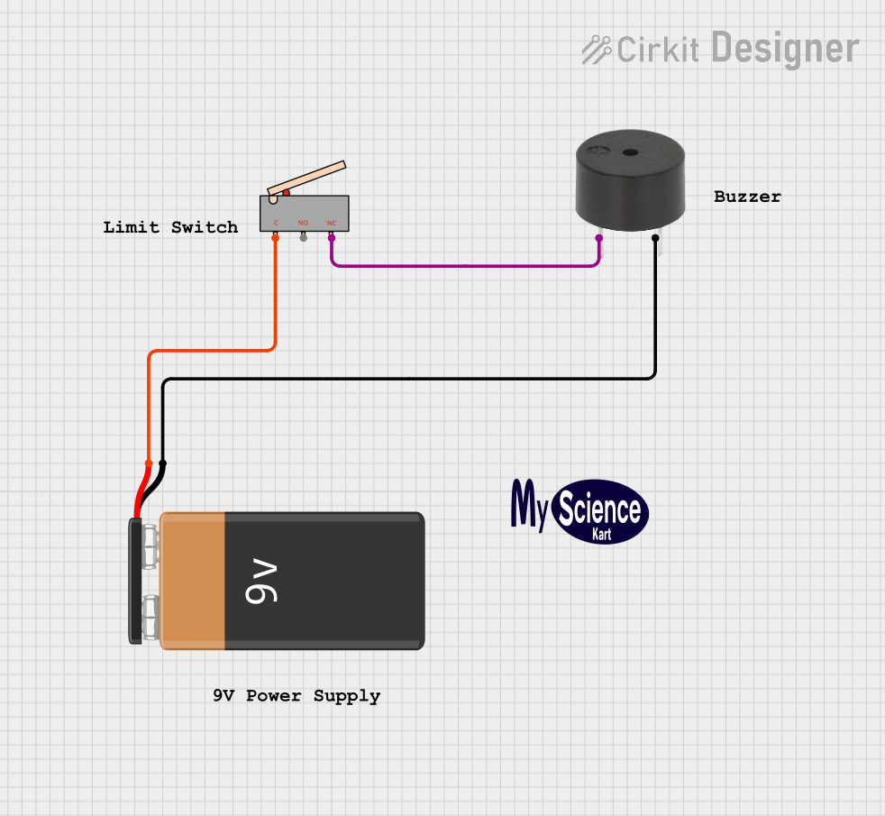 Open Project in Cirkit Designer
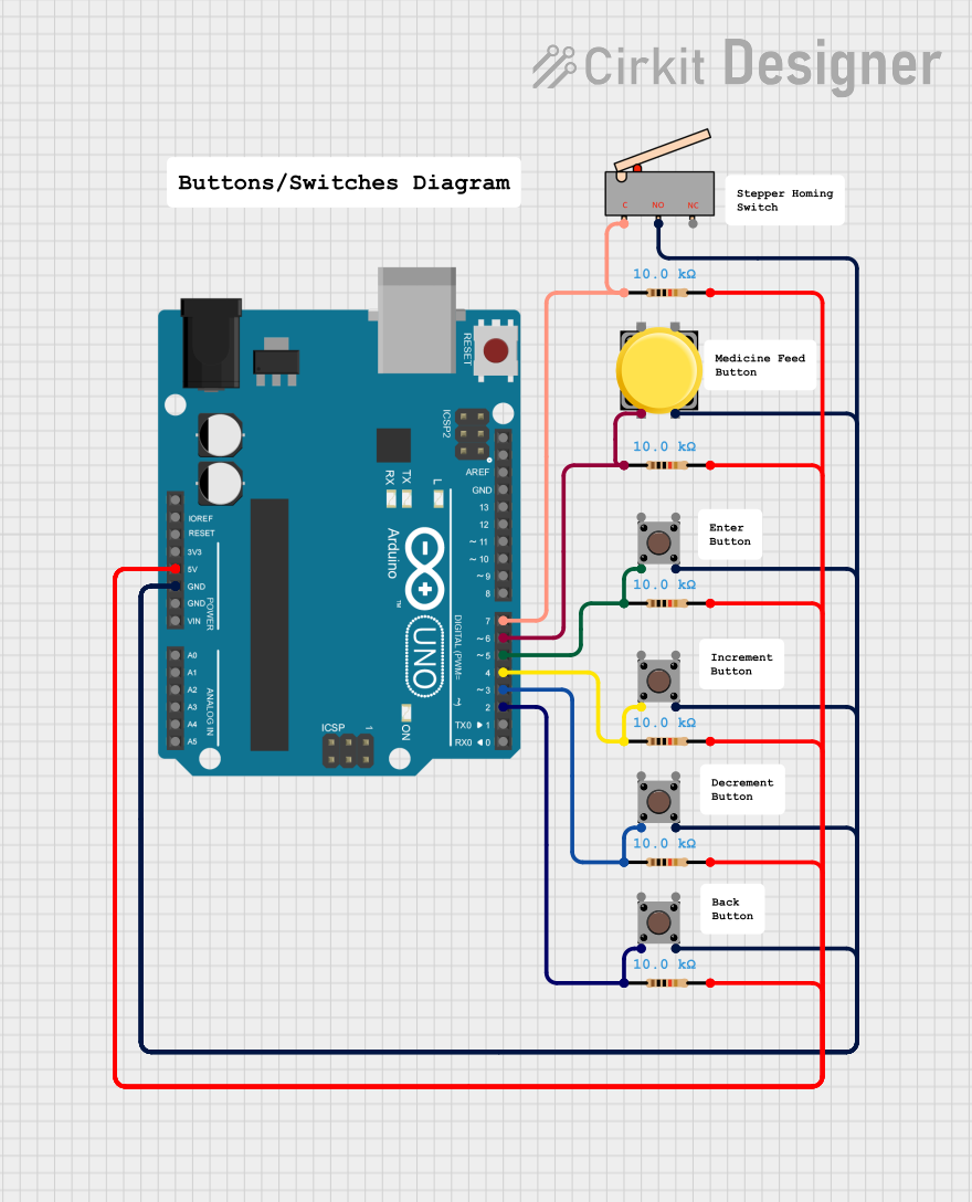 Open Project in Cirkit Designer
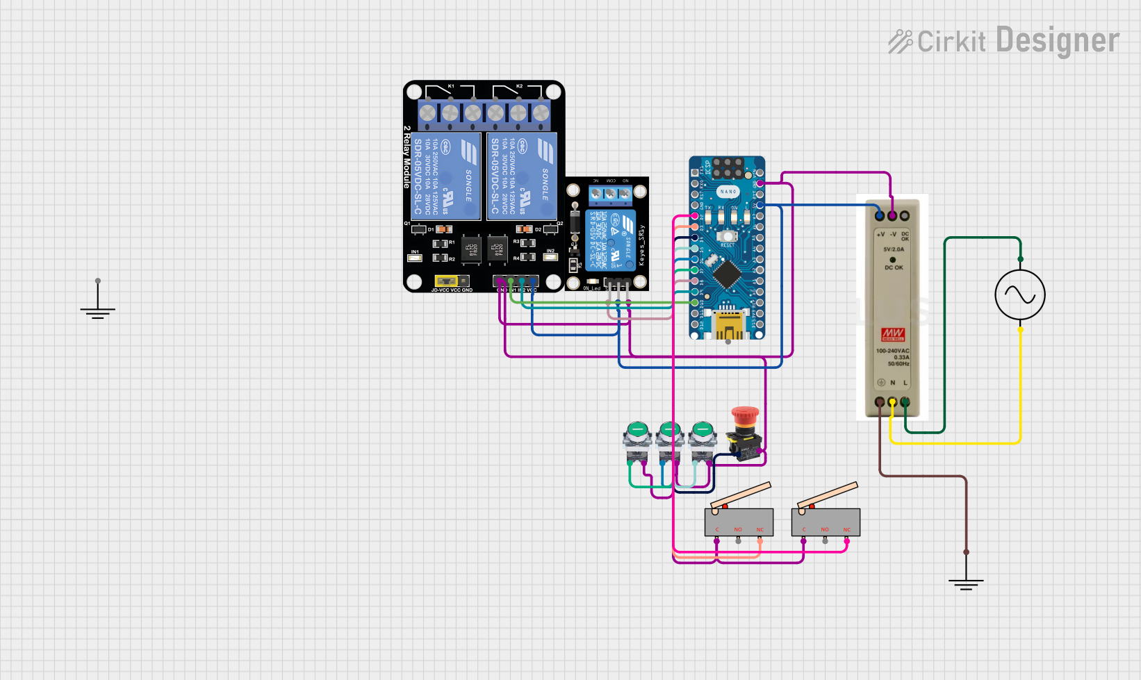 Open Project in Cirkit Designer
Explore Projects Built with Limit Switch
Open Project in Cirkit DesignerOpen Project in Cirkit DesignerOpen Project in Cirkit DesignerOpen Project in Cirkit DesignerCommon Applications and Use Cases
- Detecting the end of travel in linear or rotary motion systems
- Ensuring safety by stopping machinery when a limit is reached
- Position sensing in conveyor belts, elevators, and robotic arms
- Automating processes in manufacturing and assembly lines
- Monitoring door or hatch positions in security systems
Technical Specifications
Below are the general technical specifications for a standard limit switch. Note that specific models may vary, so always refer to the datasheet of your particular switch.
| Parameter | Value |
|---|---|
| Operating Voltage | 5V to 250V AC/DC |
| Operating Current | 0.1A to 10A (depending on model) |
| Contact Configuration | SPDT (Single Pole Double Throw) or DPDT (Double Pole Double Throw) |
| Actuator Type | Roller lever, plunger, or whisker |
| Mechanical Life | 1 million to 10 million operations |
| Electrical Life | 100,000 to 1 million operations |
| Operating Temperature | -25°C to 85°C |
| Mounting Style | Panel or surface mount |
Pin Configuration and Descriptions
The pin configuration of a limit switch typically includes three terminals: Common (COM), Normally Open (NO), and Normally Closed (NC). Below is a description of each terminal:
| Pin | Description |
|---|---|
| COM | Common terminal where the input voltage or signal is connected. |
| NO | Normally Open terminal; the circuit is open until the actuator is engaged. |
| NC | Normally Closed terminal; the circuit is closed until the actuator is engaged. |
Usage Instructions
How to Use the Limit Switch in a Circuit
- Identify the Terminals: Locate the COM, NO, and NC terminals on the limit switch.
- Connect the Circuit:
- For a normally open configuration, connect the load between the NO and COM terminals.
- For a normally closed configuration, connect the load between the NC and COM terminals.
- Mount the Switch: Secure the limit switch in the desired position using screws or brackets. Ensure the actuator aligns with the moving part it will detect.
- Test the Operation: Manually engage the actuator to verify that the circuit opens or closes as expected.
Important Considerations and Best Practices
- Voltage and Current Ratings: Ensure the switch is rated for the voltage and current in your circuit to avoid damage.
- Debouncing: Mechanical switches may produce noise or "bouncing" when actuated. Use a capacitor or software debouncing in microcontroller applications.
- Environmental Conditions: Choose a limit switch with appropriate IP (Ingress Protection) ratings for dusty, wet, or harsh environments.
- Alignment: Properly align the actuator with the moving part to ensure reliable operation.
Example: Connecting a Limit Switch to an Arduino UNO
Below is an example of how to connect a limit switch to an Arduino UNO to detect the position of a moving part.
Circuit Diagram
- Connect the COM terminal of the limit switch to the GND pin of the Arduino.
- Connect the NO terminal of the limit switch to digital pin 2 on the Arduino.
- Use a pull-up resistor (10kΩ) between digital pin 2 and the 5V pin of the Arduino.
Arduino Code
// Define the pin connected to the limit switch
const int limitSwitchPin = 2;

// Variable to store the state of the limit switch
int switchState = 0;

void setup() {
  // Set the limit switch pin as input
  pinMode(limitSwitchPin, INPUT);

  // Start the serial communication for debugging
  Serial.begin(9600);
}

void loop() {
  // Read the state of the limit switch
  switchState = digitalRead(limitSwitchPin);

  // Check if the limit switch is pressed
  if (switchState == HIGH) {
    Serial.println("Limit switch is NOT pressed.");
  } else {
    Serial.println("Limit switch is pressed!");
  }

  // Add a small delay to avoid spamming the serial monitor
  delay(100);
}
Troubleshooting and FAQs
Common Issues and Solutions
The limit switch does not respond when actuated:
- Check the wiring and ensure the connections are secure.
- Verify that the voltage and current ratings of the switch match your circuit.
- Test the switch with a multimeter to confirm its functionality.
The Arduino does not detect the switch state:
- Ensure the pull-up resistor is correctly connected to the NO terminal.
- Verify that the correct pin number is defined in the Arduino code.
- Check for loose connections or damaged wires.
Switch produces erratic or noisy signals:
- Use a capacitor (e.g., 0.1µF) across the switch terminals to reduce noise.
- Implement software debouncing in your microcontroller code.
FAQs
Q: Can I use a limit switch with high-voltage AC circuits?
A: Yes, but ensure the switch is rated for the voltage and current of your AC circuit. Use proper insulation and safety precautions.
Q: What type of actuator should I choose?
A: The actuator type depends on your application. Roller levers are ideal for sliding or rotating parts, while plungers are better for direct contact.
Q: How do I test a limit switch with a multimeter?
A: Set the multimeter to continuity mode. Connect the probes to the COM and NO terminals, then actuate the switch. The multimeter should beep when the circuit closes. Repeat for the NC terminal.
By following this documentation, you can effectively integrate a limit switch into your projects and troubleshoot common issues.